The Nikon D50 Digital Camera Review:
Sensor Noise, Dynamic Range, and Full Well Analysis
by Roger N. Clark
All images, text and data on this site are copyrighted.
They may not be used except by written permission from Roger N. Clark.
All rights reserved.
This page shows an analysis of noise, dynamic range, and full well capacity
of a Nikon D50 camera. Raw data were kindly supplied by Duncan
Munro who gave permission to use the data for thiS analysis and its
publication.
Procedures for performing this analysis are described in:
Procedures for Evaluating Digital Camera Noise, Dynamic Range, and Full
Well Capacities; Canon 1D Mark II Analysis
The lowest possible noise from a
system detecting light is the noise due to Poisson statistics
from the random rate of arrival of photons. This is called
photon statistics, or photon noise. Noise from the electronics
will add to the photon noise. We will see that
the Nikon D50 is limited by photon statistics at high
signal levels and by electronic noise from reading the sensor
(called readout noise) at very low signal levels.
In the case of high signal levels, a system that is photon statistics
limited enables us to directly measure how many photons
the sensor captures, and by increasing the exposure, we can
determine how many photons are required to saturate the
sensor. That is called the full well capacity.
With data on the lowest noise to the highest signal, we can then
determine the dynamic range of the sensor.
Results
Results for determining read noise is shown in Table 1. Column B is the
gain derived from high signal data. Gains at ISOs
higher than 200 are scaled relative to that at ISO 200. Read noise,
Column C was determined from exposures with zero light on the sensor.
Maximum signal, column D, is 30,490 electrons at ISO 200.
Dynamic range, Column E = maximum signal / read noise.
Higher ISO reduces the maximum electrons
relative to ISO 200 (e.g. ISO 400 sees half the electrons of ISO 200).
The maximum signal-to-noise ratio, Column F, is the square root of the
number of maximum photons recorded (e.g. square root 30,490 at ISO 200)
(read noise is negligible for the high signal case).
Table 1: Nikon D50 Read Noise and Dynamic Range
 A        B              C          D         E           F
        Camera       Apparent
ISO     Gain        Read Noise   Maximum   Dynamic    Maximum
     (electrons/    (electrons)  Signal     Range    Signal-to-Noise
       12-bit DN)              (electrons)              Ratio

 200     7.45          13.4      30,490     2275        175
 400     3.72                    15,240                 123
 800     1.86           7.47      7,600     1020         87
1600     0.93                     3,800                  62
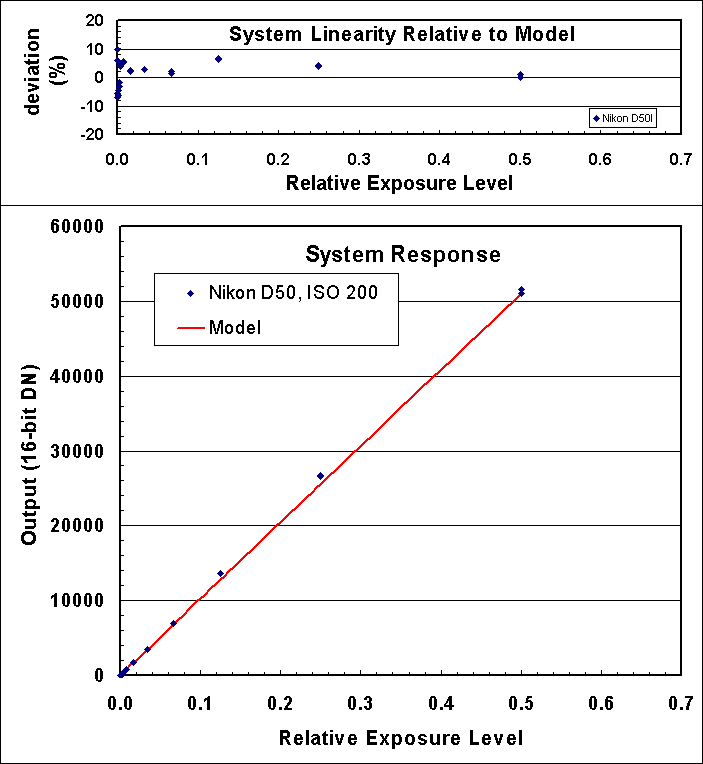
The system linearity is shown in Figure 1, and
is very good. System linearity includes the detector
linearity, shutter reproducibility, f/stop reproducibility, and light
source stability.
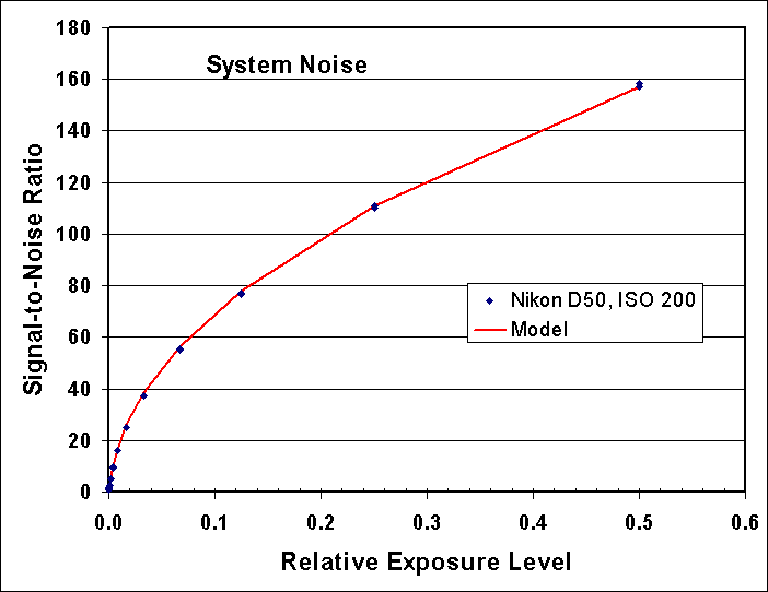
The signal-to-noise ratio as a function of intensity is
shown in Figure 2. If the sensor is photon noise limited, the trend
in this ratio is a square root dependence.
If the system is photon noise limited, the signal-to-noise
ratio squared directly equals the number of photons collected
without needing gain conversions, or computing the slope of a line.
The fact that the model matches the data very well indicates
there are no other sources of noise contributing to the data at any
significant level. Thus, for high signal levels, the Nikon D50 is
photon noise limited. This means further improvements in electronics
will not improve the signal-to-noise ratio for high signal levels.
If the quantum efficiency were improved with a different sensor, that
would certainly improve the signal-to-noise ratio.

Figure 1. The Nikon D50 shows a very linear trend with signal.
Variations in signal level include repeatability of the shutter and aperture,
as well as the light source.
The model is the average high signal DN scaled according to exposure
time and subtract read noise.

Figure 2. Signal-to-noise ratio observed and predicted. The prediction
model uses photon statistics and read noise.
Model is average DN scaled to electrons plus read noise. For this case,
ISO 200, the gain is 7.45 electrons/DN, and the read noise is 13.4 electrons.

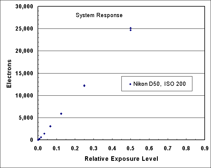
Figure 3. The electrons converted by the Nikon D50 sensor
are shown relative to exposure level. The sensor saturates at about
30,490 electrons, but is quite linear below that level.
Dark Current and Related Noise
Another noise component is due to dark current, which will
increase with exposure time. Dark current and its noise is
also a function of the temperature of the sensor and associated
electronics.
Data to be added.
The noise model is:
N = (P + r2 + t2)1/2, (eqn 1)
Where N = total noise in electrons, P = number of photons, r = read noise
in electrons, and t = thermal noise in electrons. Noise from a stream of
photons, the light we all see and image with our cameras, is the square root
of the number of photons, so that is why the P in equation 1 is not squared
(sqrt(P)2 = P).
Conclusions
The data shown here for the Nikon D50 shows that the camera is
operating and near perfect levels for the sensor. This means that for
high signals, noise is dominated by photon statistics. Noise at low
signal levels can be improved, but is quite good. To achieve higher
signal-to-noise ratio images, a higher quantum efficiency sensor with
a larger full well would be needed. Without increasing the full well
capacity, the maximum signal-to-noise ratio would not improve, but
the signal-to-noise ratio at ISO 200 could be achieved at higher
ISOs if the quantum efficiency were improved. Improvements in quantum
efficiency of about 3 are possible (Reference 2).
References
1)
CCD Gain. http://spiff.rit.edu/classes/phys559/lectures/gain/gain.html
2)
Charge coupled CMOS and hybrid detector arrays
http://huhepl.harvard.edu/~LSST/general/Janesick_paper_2003.pdf
3)
Canon EOS 20D vs Canon EOS 10D and
Canon 10D / Canon 20D / Nikon D70 / Audine comparison
http://www.astrosurf.org/buil/20d/20dvs10d.htm
4)
http://www.photomet.com/library_enc_fwcapacity.shtml
5)
Astrophotography Signal-to-Noise with a Canon 10D Camera
http://clarkvision.com/astro/canon-10d-signal-to-noise
Notes:
DN is "Data Number." That is the number in the file for each
pixel. I'm quoting the luminance level (although red, green
and blue are almost the same in the cases I cited).
16-bit signed integer: -32768 to +32767
16-bit unsigned integer: 0 to 65535
Photoshop uses signed integers, but the 16-bit tiff is
unsigned integer (correctly read by ImagesPlus).
Back to:
Digital Camera Sensor Analysis pages on this site:
http://clarkvision.com/articles/index.html#sensor_analysis
http://clarkvision.com/reviews/evaluation-nikon-d50
First published March 5, 2006.
Last updated March 6, 2006


