ClarkVision.com
| Home | Galleries | Articles | Reviews | Best Gear | Science | New | About | Contact |
Understanding DSLR Autofocus
(Phase Detect Autofocus)
by Roger N. Clark
| Home | Galleries | Articles | Reviews | Best Gear | Science | New | About | Contact |
by Roger N. Clark
An understanding of how Phase Detect Autofocus works will enable you to achieve more accurate autofocus in the field on fast moving subjects as well as understanding when distracting elements might confuse the autofocus system.
The Action Photography Series:
Introduction
Quick, pretend you are the camera and determine the correct focus point from the plot in Figure 1, below! The data in the plot represents all you have to work with. You need to make the determination in a couple of milliseconds and command the lens to go to that point so the photographer can get the picture. If in a servo mode, the data in the plot will be changing with time and you also need to determine the velocity of the subject and where the subject will be at the time the shutter actually opens, compensating for all the mechanical delays in the system, including the time to raise the mirror. Which point did you choose (1, 2 or 3)? Which point do you think the photographer wants focused? Depending on the situation, what the camera chooses and what you wanted to focus on may be very different. It is amazing that focus is as accurate as it is with such simple data. And it is truly impressive how fast it is in a good DSLR.
It is important to understand the sensitive area of your camera's autofocus system in a DSLR with phase detect Autofocus and just how the system works. Autofocus (AF) that is poorly understood will likely lead to errors in focus on your subject.
The AF sensitive region is much larger than the AF rectangle. Phase detect AF uses an out of focus part of the incoming light cone from the lens so sees a larger diffuse zone that is 2 or more times the size of the AF rectangle.
Basics of Phase Detect Autofocus (PDAF)
While the precise details of any camera or manufacturers AF sensors might be different than presented here, the basic principles are fundamental. The basic design of a phase detect system are shown in Figure 2.
The advantage of this complex system is that with a single reading by the phase detect sensors the system measures exactly how far out of focus the lens is and which direction to move the lens to achieve focus in an ideal case. With two successive readings, the velocity can be determined, and with 3 successive readings, the accelerations can be determined, all within a few milliseconds. That makes DSLR PDAF systems ideal for tracking moving subjects. I say ideal case, because if there are two subjects at different distances, the system can get confused as to which object the photographer wants to focus on. For example, if there is a stick in front of an animal, the system might focus on the stick and not the animal, or oscillate between the two with small changes in the position of the AF sensor on the subject. Thus it is important to understand the limits of the PDAF system and the active area of the AF sensors to avoid the system seeing other objects near the AF sensitive area.
In the above paragraph I specifically mentioned DSLR PDAF. There is also on-sensor PDAF in some DSLRs (for use during video), and in some mirrorless cameras. PDAF works by measuring independently the light from each side of the lens, so PDAF only works when the PDAF sensors can see each side of the lens, and that can be done only when the PDAF sensors are intercepting the light cone from the lens away from actual focus. When the subject is in focus with on-sensor PDAF, light from both sides of the lens is mixed in the circle of confusion near focus. Thus, on-sensor PDAF loses phase information when the subject is in focus (and when near focus in the circle of confusion). The on-sensor PDAF therefore can't track a moving subject and keep the subject in perfect focus all the time; it must let the focus drift off enough to get new phase information to re-acquire focus.
In Figure 2, we see that light passes through the lens which focuses a spot on the far-away subject to a spot in the focal plane. In a DSLR, the mirror one sees when looking into the camera body (e.g. with no lens on the camera) is a partially transmitting mirror (a beamsplitter). Some light is reflected up to the pentaprism where the image is erected for presentation to the eye of the photographer, and where the AF rectangles are shown in the field of view. Also up there may be the light metering sensors.
Light that passes through the beamsplitter mirror is reflected by another mirror that reflects light onto the AF sensors in the bottom of the camera body. The AF sensors work by placing two masks the mask out most of the light from the lens except for two areas on each side of the lens. In or behind the masks are lenses that focus light from each side of the lens onto a linear array. The masks block all light from the lens except for the light from small zones from two different sides of the lens (Figure 3). The lenses at the mask openings intercept the light independently from each side of the lens before the light comes to a focus. Each AF lens focuses the light from one side of the lens onto a linear AF sensor array. As the lens moves in and out of focus the pattern on the two AF sensors changes. When the pattern at a particular point on the linear array matches the mirror image on the other array, that indicates a match and possibly correct focus.
The system needs calibrating. Let's say the two linear arrays in Figure 1 are 40 pixels long and we say the correct focus is when the patterns patch at pixel 20. We obtain an image and see that the focus is actually at a different location, say at pixel 17. So we instruct the camera that when the patterns match at pixel 17, the focus is correct. From a user point of view, we can call pixel 20 zero adjustment, and then pixel 17 would be -3 (out of a range from -20 to +20). This is microadjustment. The reason for microadjustment is the distance the light travels from the beamsplitter mirror to the AF sensor may be slightly different (a few tens of microns) different than the distance from the beamsplitter to the camera's image sensor at the back of the camera. Note these distances can change with temperature as the different components and the camera body expands and contracts with temperature. Thus microadjustment may change with temperature. Indeed, there is direct evidence for microadjustment temperature sensitivity; see: Fast Simple on Site Microadjustment Methods.

The sensitivity of the AF system to proper focus is dependent on the angle of convergence of the light cone from the lens. The further apart the AF sensor masks, the greater the sensitivity. The system is not dependent on the amount of light, except when light levels get too low, noise (both photon noise and sensor noise) could compromise the signals. Many cameras have some sensors sensitive to f/2.8 lenses, and such AF sensors have the masks further apart (Figure 4). This configuration provides greater accuracy in the focus determination.
AF at f/8 has more to do the the position and size of the AF masks, than it has to do with light level. However, as f/8 focusing is usually receiving less light as the masks usually only include a smaller part of the lens, AF at f/8 usually can not do was well at lower light levels as can and f/5.6 or faster lens.
As the AF system in cameras must work over a variety of lens f/ratios. the masks for the AF system must let in a range of light angles. Also, a larger mask lets in more light from the lens, enabling AF at lower light levels. Thus, there is a design trade in large enough masks to work over a range of f/ratios, enough light for a good signal, but a small enough mask aperture for AF phase accuracy. This combination has a side effect, with the masks being not in the focal plane, but in the out-of-focus light cone from the lens, that off-angle light gets into the system too (Figure 6). This means that the edges of the AF sensitive zone for a single AF sensor has a diffuse boundary. That boundary is larger than the typical AF rectangle we see in the DSLR viewfinder. Note too that the AF rectangles are in the pentaprism assembly at the top of the camera and the AF sensors at the bottom. Thus, the visible AF rectangles might be slightly misaligned from the actual AF sensitive region, although I have never observed a significant shift in the cameras I have tested.
Manufacturer's Published Data
The actual AF sensor is larger (at least in some cameras), than the AF rectangle.
See page 19 of the Canon 1D Mark IV white paper which shows the active AF
region is larger than the AF rectangle:
http://www.learn.usa.canon.com/resources/products/eos_1d_markiv/eos_1dmarkiv_white_papers.shtml
See: EOS1D_MarkIV-WP1.pdf and look at page 19 of the PDF.
Similarly, the white papers for the Canon 1DX and 5D Mark III also show AF sensors
larger than the AF rectangle. Foe example, see
http://www.learn.usa.canon.com/resources/articles/2012/1dx_guidebook.shtml?categoryID=12
and get the EOS-1D X AF Settings Guidebook (Updated June 2012):
EOS_1DX_AF_Guide_CDLC_Updated_June_2012.pdf.
The AF diagram is on page 36 of the PDF.
The Canon 50D and 5D Mark II white paper, EOS50D_5D-MarkII-WP2.pdf, shows similar diagrams with the AF sensor being larger than the AF rectangle. For example, see page 31 of the PDF for the 50D AF sensor diagram, and page 32 for the 5DII AF sensor diagram. The white paper can be downloaded from here: http://www.learn.usa.canon.com/resources/articles/2011/eos_white_papers.shtml.
Phase Detect AF and AF Masks in the Out-of_Focus Light Field
Note that the sensitivity extends beyond the limits of the AF sensors because the system works on the out of focus part of the light cone from the lens (Figures 2 - 6). While the sensitivity is dropping off, in that outer region, a bright, high-contrast foreground or background object could either confuse the AF system to lock onto that or throw the focus off your main subject.
A simple way to determine the active AF region is to use a small bright light in a dark background with the light being smaller than an AF rectangle in the viewfinder. For example a distant street light, with no other lights in the field of view, or the moon in a clear dark sky. Move the lens out of focus and then activate a single AF point at different distances from the AF rectangle and see how far you can be for AF to work. You may be surprised at how far the sensitivity is Be sure you have only one AF rectangle activated with no expansion. You will find the AF zone sensitivity does not have a hard edge, but AF gradually degrades once you get some distance from the AF rectangle.
Now, with that knowledge, consider the following. The AF system will "choose" the brightest high contrast subject within the diffuse active AF zone. It is very difficult to track a dark subject like black bird with brighter distracting elements in the foreground or background, especially if the bird is smaller than the AF sensitive region. It is best to wait for the subject to be closer (filling more of the frame), and/or does not have the distracting brighter elements nearby if you wanted to make an environment image.
If one tries the above experiments, one will find quite accurate AF with the subject quite outside the AF rectangle. Try it too with the moon in a daytime blue sky. You get the same result. And if it gives a false focus lock. what is to say a bright subject near an AF point when trying to focus on a bird will not cause the same thing to happen? It illustrates the problem of finding correct lock on subject with complex foregrounds or backgrounds. The point of the experiment is to show SENSITIVITY of the AF point outside the AF rectangle, not to say it provides accurate AF. In fact, as one moves away from the AF rectangle, AF accuracy falls. But that just makes the problem worse for getting accurate focus on your intended subject. A distinct subject against a smooth background, like the moon in a night or deep blue sly, is really a simple test that can be done in many ways to show the sensitivity is larger than the AF rectangle.
The AF Sensitive Area is f/ratio Dependent
A further note. The size of diffuse AF region that is larger than the AF rectangle will vary by f/ratio, with faster f/ratio being larger and more diffuse. This is not your selected f/ratio but the f/ratio of the system, as AF occurs before the aperture is closed to your selected f/ratio. Thus, the size of the AF zone will be large with an f/2.8 lens, then will decrease and become less diffuse when you add a 1.4x TC, then decrease more and be less diffuse when a 2x TC is added. Same with an f/4 lens and adding TCs.
Examples
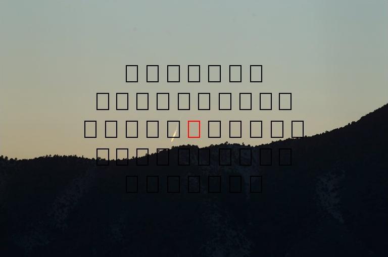
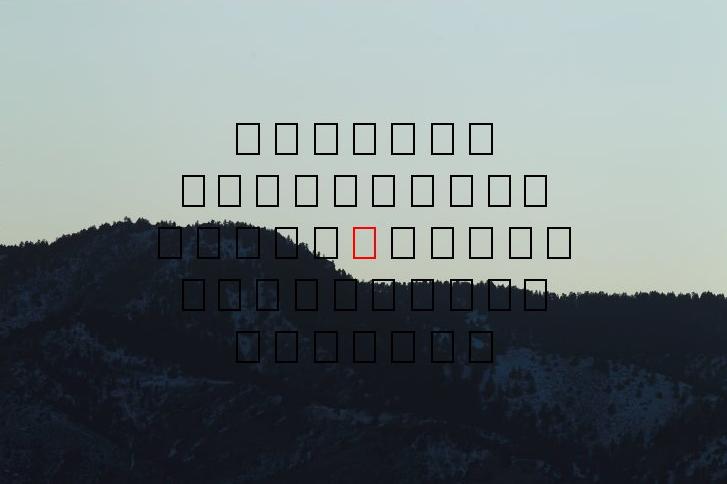
Images that show AF locks onto a nearby brighter subject outside the AF rectangle:
In the first image, AF locks onto the bright contrail that is about 1 AF rectangle away.
In the second image, AF locks onto the tree line, about 1 AF rectangle away. Dark edge on a bright bland field
In the 3rd image, AF locks onto the tree line, about 1 AF rectangle away. Bright edge on a dark bland field.
In all cases, the focus is spot on (300 f/2.8 lens with 1D Mark IV). However, increasing the distance much more and the AF accuracy drops rapidly.

See this demo from class CS178 at Stanford: http://graphics.stanford.edu/courses/cs178/applets/autofocusPD.html Be sure to play with the focus slider. Note that the two lenses, labeled Micro Lens 1 and Micro Lens 2 are not in the focal plane. These are apertures that restrict light from each side of the lens. In a real scene, light from other parts of the lens and different parts of the field of view also enters these two lenses, contributing to the diffuse sensitivity of the AF system.
Conclusions
In order to do phase detect AF, one must isolate portions of the incoming light cone from each side of the lens. This can not be done in focus. It is a brilliant concept: fast focusing and focus tracking of moving subjects using out of focus information. Even when the subject is properly focused, the AF system is measuring light from the out of focus field. So whether a field stop is used outside of focus, or the collimating lenses are used as the field stop, as in the Stanford examples, both are in the out of focus field. In order to have sensitivity over a range of f/stops and focal distances, that means the optical response of the system will not have a hard edge to AF sensitivity. Above is direct evidence of this effect. Every camera I have tested behaves the same from film SLRs to the latest DSLR cameras.
It all comes down to understanding your equipment and working around any limitations.
The Action Photography Series:
| Home | Galleries | Articles | Reviews | Best Gear | Science | New | About | Contact |
http://clarkvision.com/articles/understanding.autofocus
First Published March 12, 2013
Last updated May 31, 2023.