| Home | Galleries | Articles | Reviews | Best Gear | Science | New | About | Contact |
| Home | Galleries | Articles | Reviews | Best Gear | Science | New | About | Contact |
Derived from Chapter 1 in: Manual of Remote Sensing
John Wiley and Sons, Inc, A. Rencz, Editor, New York, 1999
This book chapter was produced by personel of the US Government
therefore it can not be copyrighted and is in the public domain.
How to Reference:
Clark, R. N., Chapter 1: Spectroscopy of Rocks and Minerals, and
Principles of Spectroscopy, in Manual of Remote Sensing, Volume 3,
Remote Sensing for the Earth Sciences, (A.N. Rencz, ed.) John Wiley
and Sons, New York, p 3- 58, 1999.
1.2 Absorption and Scattering.
1.5 Atmospheric Transmittance: Windows for Remote Sensing.
2. THE REFLECTION AND ABSORPTION PROCESSES
2.1 Reflection and Absorption..
3.1.2 Charge Transfer Absorptions..
4. SPECTRA OF MISCELLANEOUS MINERALS AND MATERIALS
5. THE SENSITIVITY OF ABSORPTION BANDS TO CRYSTAL STRUCTURE AND CHEMISTRY
6.3 The Continuum and Band Depth.
6.4 Continuum-Removed Spectral Feature Comparison.
6.5 Other Spectral Variability and Rules.
6.5.3 Iron Oxide, Hydroxide, Sulfate Complexity..
7. QUANTITATIVE UNDERSTANDING: RADIATIVE TRANSFER THEORY.
9. CONCLUSIONS AND DISCUSSION.
1.1 About This Chapter. Spectroscopy is the study of light as a function of wavelength that has been emitted, reflected or scattered from a solid, liquid, or gas. In this chapter I will primarily discuss the spectroscopy of minerals, but the principles apply to any material. No single chapter can cover this topic adequately, and one could argue, not even a single book. Thus, in some ways, this chapter may fall short of expectations, depending on the reader. In this chapter, I have tried to provide an overview of what is already known, some of which may be covered better in other reviews. I have also tried to present some of the practical lessons of spectroscopy, some of which have been in use by spectroscopists as common knowledge, but have not necessarily been previously published in detail. See Adams (1975), Hunt (1977), Farmer (1974), Hunt (1982); Clark and Roush (1984), Clark et al. (1990a), Gaffey et al. (1993), Salisbury (1993), and references in those papers for more details.
1.2 Absorption and Scattering. As photons enter a mineral, some are reflected from grain surfaces, some pass through the grain, and some are absorbed. Those photons that are reflected from grain surfaces or refracted through a particle are said to be scattered. Scattered photons may encounter another grain or be scattered away from the surface so they may be detected and measured. Photons may also originate from a surface, a process called emission. All natural surfaces emit photons when they are above absolute zero. Emitted photons are subject to the same physical laws of reflection, refraction, and absorption to which incident photons are bound.
Photons are absorbed in minerals by several processes. The variety of absorption processes and their wavelength dependence allows us to derive information about the chemistry of a mineral from its reflected or emitted light. The human eye is a crude reflectance spectrometer: we can look at a surface and see color. Our eyes and brain are processing the wavelength-dependent scattering of visible-light photons to reveal something about what we are observing, like the red color of hematite or the green color of olivine. A modern spectrometer, however, can measure finer details over a broader wavelength range and with greater precision. Thus, a spectrometer can measure absorptions due to more processes than can be seen with the eye.
1.3 Spectroscopy Terms. There are 4 general parameters that describe the capability of a spectrometer: 1) spectral range, 2) spectral bandwidth, 3) spectral sampling, and 4) signal-to-noise ratio (S/N). Spectral range is important to cover enough diagnostic spectral absorptions to solve a desired problem. There are general spectral ranges that are in common use, each to first order controlled by detector technology: a) ultraviolet (UV): 0.001 to 0.4 µm, b) visible: 0.4 to 0.7 µm, c) near-infrared (NIR): 0.7 to 3.0 µm, d) the mid-infrared (MIR): 3.0 to 30 µm, and d) the far infrared (FIR): 30 µm to 1 mm (e.g. see The Photonics Design and Applications Handbook, 1996 and The Handbook of Chemistry and Physics, any recent year). The ~0.4 to 1.0-µm wavelength range is sometimes referred to in the remote sensing literature as the VNIR (visible-near-infrared) and the 1.0 to 2.5-µm range is sometimes referred to as the SWIR (short-wave infrared). It should be noted that these terms are not recognized standard terms in other fields except remote sensing, and because the NIR in VNIR conflicts with the accepted NIR range, the VNIR and SWIR terms probably should be avoided. The mid-infrared covers thermally emitted energy, which for the Earth starts at about 2.5 to 3 µm, peaking near 10 µm, decreasing beyond the peak, with a shape controlled by grey-body emission.
Spectral bandwidth is the width of an
individual spectral channel in the
spectrometer. The narrower the spectral
bandwidth, the narrower the absorption
feature the spectrometer will accurately
measure, if enough adjacent spectral
samples are obtained. Some systems have
a few broad channels, not contiguously
spaced and, thus, are not considered
spectrometers (Figure 1a). Examples
include the Landsat Thematic Mapper
(TM) system and the MODerate Resolution
Imaging Spectroradiometer (MODIS),
which can't resolve narrow absorption
features. Others, like the NASA JPL
Airborne Visual and Infra-Red Imaging
Spectrometer (AVIRIS) system have many
narrow bandwidths, contiguously spaced
(Figure 1b). Figure 1 shows spectra for the
mineral alunite that could be obtained by
some example broadband and spectrometer
systems. Note the loss in subtle spectral
detail in the lower resolution systems
compared to the laboratory spectrum.
Bandwidths and sampling greater than 25
nm rapidly lose the ability to resolve
important mineral absorption features. All
the spectra in Figure 1b are sampled at half
Nyquist (critical sampling) except the Near
Infrared Mapping Spectrometer (NIMS),
which is at Nyquist sampling. Note,
however, that the fine details of the
absorption features are lost at the ~25 nm
bandpass of NIMS. For example, the
shoulder in the 2.2-µm absorption band is
lost at 25-nm bandpass. The Visual and
Infrared Mapping Spectrometer (VIMS)
and NIMS systems measure out to 5 µm,
thus can see absorption bands not
obtainable by the other systems.
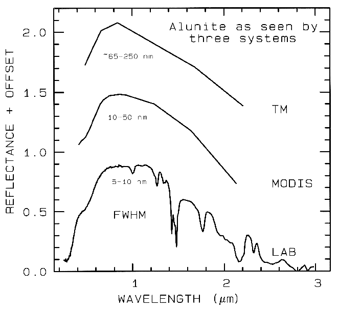
Figure 1a. Spectra of the mineral alunite is shown as measured
in the laboratory and for broad-band remote sensing instruments
(see text). The FWHM is
the Full Width at Half Maximum, defined in Figure 2. The alunite
is sample HS295.3B from the
USGS spectral library (Clark et al, 1993b).
Each spectrum is offset upward 0.6 units
from the one below it for clarity.
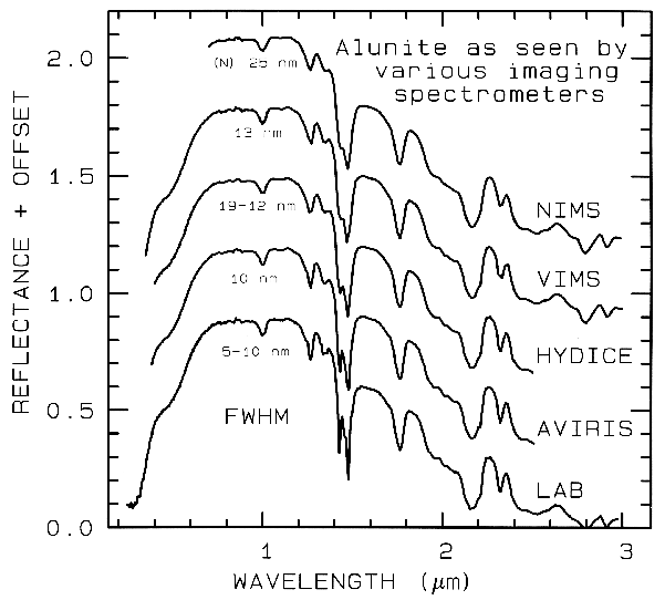 Figure 1b.
Figure 1b. Spectra of the mineral alunite is shown as measured
in the laboratory and for
some imaging spectrometers (see text and Figure 1a). Note: the
NIMS and VIMS systems measure to 5
µm. Each spectrum is offset upward
0.3 units from the one below it for
clarity.
The shape of the bandpass profile is
also important. Ideally each spectrometer
channel rejects all light except that from
within a given narrow wavelength range,
but occasionally, due to optical effects too
complex to discuss in detail here, light may
leak in from out of the bandpass (e.g.
scattering within the optical system, or
inadequate blocking filters). The most
common bandpass in spectrometers is a
Gaussian profile. While specific
spectrometer designs may have well-defined theoretical bandpass profiles,
aberrations in the optical system usually
smears the profile closer to a Gaussian
shape. The width of the bandpass is
usually defined as the width in wavelength
at the 50% response level of the function,
as shown in Figure 2, called the Full Width
at Half Maximum (FWHM).
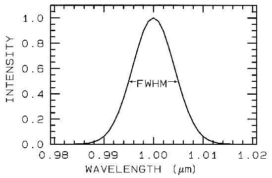 Figure 2.
Figure 2. A Gaussian profile with a Full Width at Half
Maximum (FWHM) of 10 nm is shown.
This profile is typical of spectrometers such as AVIRIS
which has 224 such profiles spaced at about 10 nm.
Spectral sampling is the distance in wavelength between the spectral bandpass profiles for each channel in the spectrometer as a function of wavelength. Spectral sampling is often confused with bandpass, with the two lumped together and called resolution. Information theory tells us that to resolve a two spectral features, we must have two samples. Further, in order to not introduce sampling bias, the samples must be close enough together to measure the peak and valley locations. The Nyquist theorem states that the maximum information is obtained by sampling at one-half the FWHM. Spectrometer design, however, sometimes dictates a different sampling, and many modern spectrometers in use (e.g. AVIRIS, VIMS) sample at half-Nyquist: sampling interval approximately equal to the FWHM. Note that the AVIRIS system has a bandpass ~0.01 µm (10 nm), a sampling of ~0.01 µm, and thus has a spectral resolution of ~0.02 µm (20 nm). The NIMS system in Figure 1 can sample at Nyquist (shown), half-Nyquist, and lower.
Finally, a spectrometer must measure the spectrum with enough precision to record details in the spectrum. The signal-to-noise ratio (S/N) required to solve a particular problem will depend on the strength of the spectral features under study. The S/N is dependant on the detector sensitivity, the spectral bandwidth, and intensity of the light reflected or emitted from the surface being measured. A few spectral features are quite strong and a signal to noise of only about 10 will be adequate to identify them, while others are weak, and a S/N of several hundred (and higher) are often needed (Swayze et al., 1997).
1.4 Imaging Spectroscopy. Today, spectrometers are in use in the laboratory, in the field, in aircraft (looking both down at the Earth, and up into space), and on satellites. Reflectance and emittance spectroscopy of natural surfaces are sensitive to specific chemical bonds in materials, whether solid, liquid or gas. Spectroscopy has the advantage of being sensitive to both crystalline and amorphous materials, unlike some diagnostic methods, like X-ray diffraction. Spectroscopy's other main advantage is that it can be used up close (e.g. in the laboratory) to far away (e.g. to look down on the Earth, or up at other planets). Spectroscopy's historical disadvantage is that it is too sensitive to small changes in the chemistry and/or structure of a material. The variations in material composition often causes shifts in the position and shape of absorption bands in the spectrum. Thus, with the vast variety of chemistry typically encountered in the real world, spectral signatures can be quite complex and sometimes unintelligible. However, that is now changing with increased knowledge of the natural variation in spectral features and the causes of the shifts. As a result, the previous disadvantage is turning into a huge advantage, allowing us to probe ever more detail about the chemistry of our natural environment.
With the advances in computer and detector technology, the new field of imaging spectroscopy is developing (Goetz et al., 1985, Vane et al., 1993; Green et al., 1990; Mustard and Sunshine, 1997: Chapter 5; Kruse 1997: Chapter 15 and references therein). Imaging spectroscopy is a new technique for obtaining a spectrum in each position of a large array of spatial positions so that any one spectral wavelength can be used to make a recognizable image. The image might be of a rock in the laboratory, a field study site from an aircraft, or a whole planet from a spacecraft or Earth-based telescope. By analyzing the spectral features, and thus specific chemical bonds in materials, one can map where those bonds occur, and thus map materials. Such mapping is best done, in this author's opinion, by spectral feature analysis.
Imaging spectroscopy has many names in the remote sensing community, including imaging spectrometry, hyperspectral, and ultraspectral imaging. Spectroscopy is the study of electromagnetic radiation. Spectrometry is derived from spectro-photometry, the measure of photons as a function of wavelength, a term used for years in astronomy. However, spectrometry is becoming a term used to indicate the measurement of non-light quantities, such as in mass spectrometry (e.g. Ball, 1995). Hyper means excessive, but no imaging spectrometer in use can hardly be considered hyper-spectral, after all, a couple of hundred channels pales in comparison to truly high resolution spectrometer with millions of channels. Ultraspectral is beyond hyperspectral, a lofty goal I do not believe we have reached. Terms like laboratory spectrometer, spectroscopist, reflectance spectroscopy, thermal emission spectroscopy, etc, are in common use. One rarely, if ever sees the converse: spectrometrist, reflectance spectrometry, etc. So it seems prudent to keep the terminology consistent with "imaging spectroscopy."
In this chapter I will introduce you to the factors affecting spectra of natural materials, including scattering and absorption, and the causes of absorption features. I'll also discuss doing quantitative estimates of mixtures, and show example spectra of minerals and other common materials that might be encountered in the natural world.
1.5 Atmospheric Transmittance:
Windows for Remote Sensing.
Any effort to
measure the spectral properties of a material
through a planetary atmosphere, must consider
where the atmosphere absorbs. For example,
the Earth's atmospheric transmittance is shown
in Figure 3. The drop toward the ultraviolet is
due to scattering and strong ozone absorption at
wavelengths short of 0.35 µm. Ozone also
displays an absorption at 9.6 µm. Oxygen
absorbs at 0.76 µm in a narrow feature. CO2
absorbs at 2.01, 2.06, and a weak doublet near
1.6 µm. Water causes most of the rest of the
absorption throughout the spectrum and hides
additional (weaker) absorptions from other
gases. The mid-IR spectrum in Figure 3b
shows the effect of doubling CO2, which in this
case is small compared to the absorption due to
water. While we will see that the spectral
region near 1.4 and 3 µm can be diagnostic of
OH-bearing minerals, we can't usually use these
wavelengths when remotely measuring spectra
through the Earth's atmosphere (it has been
done from high elevation observatories during
dry weather conditions). However, these
spectral regions can be used in the laboratory
where the atmospheric path lengths are
thousands of times smaller, or when measuring
spectra of other planets from orbiting
spacecraft.
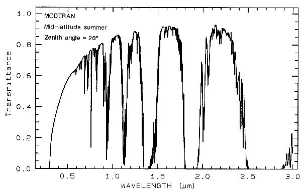
Figure 3a. Modtran (Berk et al., 1989) modeled
atmospheric transmittance, visible to near-infrared.
Most of the absorptions are due to water. Oxygen occurs
at 0.76 µm, carbon
dioxide at 2.0 and 2.06 µm. See text.
Figure 3b. Atmospheric transmittance, mid-infrared is
compared to scaled grey-body spectra.
Most of the absorption is due to water. Carbon dioxide
has a strong 15-µm band, and the dotted
line shows the increased absorption due to doubling
CO2. Also shown is the black-body emission
at 288 K and the grey-body emission from water and a
sandstone scaled to fit on this transmittance
scale. The water and sandstone curves were computed
from reflectance data using: 1 - reflectance
times a black-body at 288 Kelvin.
2. THE REFLECTION AND ABSORPTION PROCESSES
2.1 Reflection and Absorption.. When a stream of photons encounter a medium with a change in the index of refraction some are reflected and some are refracted into the medium. It is beyond this Chapter to review all the physical laws of reflection and refraction; a good optics or physics book can do that (e.g. Hecht, 1987). However, the basics of reflection should be understood. All materials have a complex index of refraction:
m = n - jK (eqn 1a)
where m is the complex index of refraction, n is the real part of the index, j = (-1)1/2, and K is the imaginary part of the index of refraction, sometimes called extinction coefficient.
When photons enter an absorbing medium, they are absorbed according to Beers Law:
I = Io e-kx, (eqn 1b)
where I is the observed intensity, Io is the original light intensity, k is an absorption coefficient and x is the distance traveled through the medium.
The absorption coefficient is related to the complex index of refraction by the equation:
k = 4 pi K/Lambda, (eqn 1c)
where Lambda is the wavelength of light. Example index of refraction, n, and extinction coefficient, K are shown in Figure 4a for quartz. The reflection of light, R, normally incident onto a plane surface is described by the Fresnel equation:
R = [(n - 1)2 + K2 ] / [(n + 1)2 + K2 ]. (eqn 1d)
At angles other than normal, the reflectance is
a complex trigonometric function involving the
polarization direction of the incident beam and
is left to the reader to study in standard optics or
physics text books. The reflection from quartz
grains as measured on a laboratory spectrometer
is shown in Figure 4b. While the spectrum is of
a particulate surface, first surface reflection
dominates all wavelengths, and so is similar to
the spectrum of a slab of quartz.
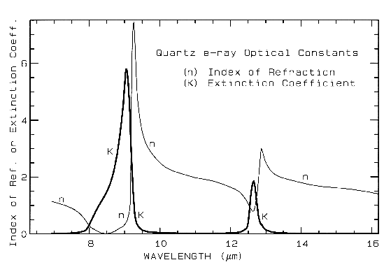
Figure 4a. Optical constants of quartz, SiO2, from Spitzer and Klienman, 1960.
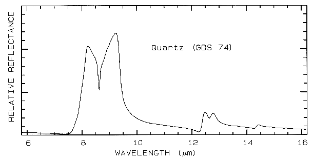
Figure 4b. Relative reflectance of powdered quartz.
The absorption coefficient is traditionally expressed in units of cm-1 and x in cm. Equations 1a-d hold for a single wavelength. At other wavelengths, the absorption coefficient and index of refraction are different, and the observed reflected intensity varies. The absorption coefficient as a function of wavelength is a fundamental parameter describing the interaction of photons with a material. So is the index of refraction, but it generally varies less than the absorption coefficient as a function of wavelength, especially at visible and near-infrared wavelengths. At fundamental absorption bands, both n and K vary strongly with wavelength, as seen in Figure 4a, though K still varies over more orders of magnitude than n.
The complex index of refraction in Figure 4a shows important properties of materials. As one moves to longer wavelengths (left to right in Figure 4a), the index of refraction decreases to a minimum just before a sharp rise (e.g. at 8.5 and 12.6 µm in Figure 4a). The minimum is often near or even below n = 1. The wavelength where n = 1 is called the Christensen frequency and usually results in a minimum in reflected light because of the small (to zero) difference in the index of refraction compared to the surrounding medium (e.g. air or vacuum). The location of the observed reflectance minimum is also controlled by the extinction coefficient according to equation 1d. Note that the Christensen frequency sometimes occurs at a wavelength shorter than the maximum in the extinction coefficient (e.g. Figure 4a). This maximum is called the restrahlen band: the location of fundamental vibrational stretching modes in the near and mid-infrared. The combination of n and K at these wavelengths often results in high reflectance. See Hapke (1993) for more details.
2.2 Emittance. At mid-infrared wavelengths, materials normally receive thermally-emitted photons. In the laboratory, one can shine enough light on a sample to ignore emitted photons and measure reflectance, but that can't be done in typical remote sensing situations. Measuring emitted energy in the laboratory is not easy because all materials emit energy unless cooled to very low temperatures. Trying to measure thermal emission at room temperatures would be like trying to take a picture with a camera with transparent walls and light bulbs turned on inside the camera! However, Kirchofs Law (e.g. Nicodemus, 1965) states:
E = 1 - R (eqn 1e)
where E is emissivity. Several studies have been conducted to show that the rule generally holds (e.g. see Salisbury, 1993 and references therein). While some discrepancies have been found, they may be due to the difficulty of measuring emittance or due to temperature gradients in the samples (e.g. Henderson et al., 1996 and references therein). Considering that and the fact that one rarely measures all the light reflected or emitted (usually a directional measurement is made), the law is basically true except in the most rigorous studies where absolute levels and band strengths are critical to the science. In practical terms, small changes in grain size result in spectral changes that are usually larger than the discrepancies in the law.
2.3 Summary. The complex interaction of light with matter involves reflection and refraction from index of refraction boundaries, a process we call scattering, and absorption by the medium as light passes through the medium. The amount of scattering versus absorption controls the amount of photons we receive from a surface.
What causes absorption bands in the spectra of materials? There are two general processes: electronic and vibrational. Burns (1993) examines the details of electronic processes, and Farmer (1974) covers vibrational. These two books are significant works providing the fundamentals as well as practical information. A shorter introduction to the causes of absorption bands in minerals is given by Hunt (1977, 1982) and Gaffey et al. (1993) for the visible and near-infrared.
Isolated atoms and ions have discrete energy states. Absorption of photons of a specific wavelength causes a change from one energy state to a higher one. Emission of a photon occurs as a result of a change in an energy state to a lower one. When a photon is absorbed it is usually not emitted at the same wavelength. For example, it can cause heating of the material, resulting in grey-body emission at longer wavelengths.
In a solid, electrons may be shared between individual atoms. The energy level of shared electrons may become smeared over a range of values called "energy bands." However, bound electrons will still have quantized energy states (e.g. see Burns, 1970, 1993).
3.1.1 Crystal Field Effects.
The most
common electronic process revealed in the
spectra of minerals is due to unfilled electron
shells of transition elements (Ni, Cr, Co, Fe,
etc.). Iron is the most common transition
element in minerals. For all transition
elements, d orbitals have identical energies in
an isolated ion, but the energy levels split when
the atom is located in a crystal field (e.g. see
Burns, 1970, 1993). This splitting of the orbital
energy states enables an electron to be moved
from a lower level into a higher one by
absorption of a photon having an energy
matching the energy difference between the
states. The energy levels are determined by the
valence state of the atom (e.g. Fe2+, Fe3+), its
coordination number, and the symmetry of the
site it occupies. The levels are also influenced
by the type of ligands formed, the extent of
distortion of the site, and the value of the
metal-ligand interatomic distance (e.g. Burns,
1993). The crystal field varies with crystal
structure from mineral to mineral, thus the
amount of splitting varies and the same ion (like
Fe2+) produces obviously different absorptions,
making specific mineral identification possible
from spectroscopy (Figure 5, 6, and 7).
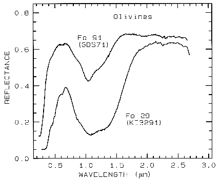 Figure 5a.
Figure 5a. Reflectance spectra of two olivines showing the
change in band position and shape with
composition. The 1-µm absorption band is due to a
crystal field absorption of Fe2+. "Fo" stands
for forsterite (Mg2SiO4) in the
forsterite-fayalite (Fe22+SiO4)
olivine solid solution series. The Fo
29 sample (KI3291 from King and Ridley, 1987) has an FeO
content of 53.65%, while the Fo 91
sample (GDS 71; labeled Twin Sisters Peak in King and
Ridley, 1987) has an FeO content of
7.93%. The mean grain size is 30 and 25 µm respectively.
The 1-µm band position varies from
about 1.08 µm at Fo 10 to 1.05 µm at Fo 90 (King and Ridley, 1987).
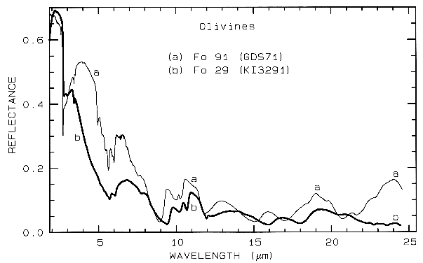
Figure 5b. Same as for Figure 5a but for mid-infrared
wavelengths. Note the shifts in the spectral
features due to the change in composition. See text for
discussion of vibrational absorption
bands.
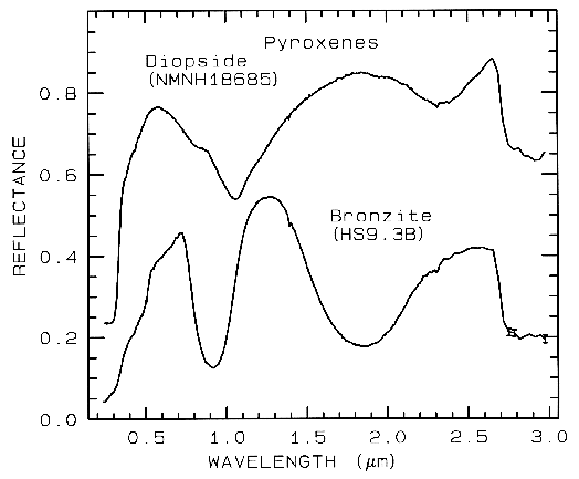 Figure 6a.
Figure 6a. Reflectance spectra of two pyroxenes showing
the change in Fe2+ -absorption band
position and shape with composition
(from Clark et al., 1993b). Diopside, sample NMNH18685,
is CaMgSi2O6, but some
Fe2+ substitutes for Mg. Bronzite,
sample HS9.3B, is (Mg,Fe)SiO3 with
mostly Mg. The 1-µm versus the 2-µm band
position of a pyroxene describes the pyroxene
composition, Figure 6c. The diopside spectrum is offset 0.2 units upward.
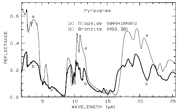
Figure 6b. Same as for Figure 6a, but for mid-infrared
wavelengths. Note the shifts in the spectral
features due to the change in composition.
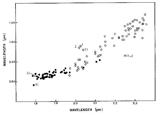
Figure 6c. Pyroxene 1-µm versus 2-µm
absorption band position as a function of composition,
as adapted from Adams (1974) by Cloutis and Gaffey (1991).
Open circles have > 11%
wollastonite (Wo), and solid symbols < 11 % Wo. Samples
with zoned or exolved phases are
marked by "Z." Other samples not following
the "normal" trend include those with >1% TiO2
(Ti), > 1% Cr2O3 (Cr),
or >4% Al2O3. From Cloutis and Gaffey (1991).
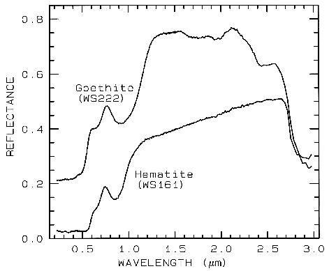 Figure 7a.
Figure 7a. Reflectance spectra of the iron oxide
hematite (Fe2O3) and iron hydroxide goethite
(FeOOH, from Clark et al., 1993b). The intense
charge-transfer band in the UV (< 0.4 µm) is
"saturated" in reflectance, so only first surface
(specular) reflection is seen in these spectra. The
0.9-µm and 0.86-µm absorption features are
due to Laporte-forbidden transitions (e.g. Morris et
al, 1985; Sherman, 1990 and references
therein). The absorption at 2.7-3 µm is due to trace water
in the samples., and in the case of goethite, the
OH. The goethite spectrum is offset upward 0.2 units.
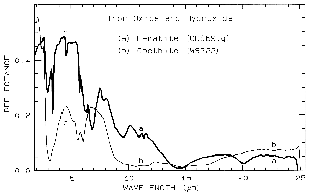
Figure 7b. Same as for Figure 7a, but for
mid-infrared wavelengths, and no offsets.
Example Fe2+ absorptions are shown in Figure 5a (olivines), and Figure 6a (pyroxenes). Note the shift in band position and shape between the different compositions. Example Fe3+ absorptions are shown in goethite (FeOOH) and hematite (Fe2O3) in Figure 7a. Compositional changes also shift vibrational absorptions, discussed below, and as seen in Figures 5b, 6b, and 7b. The compositional shifts of the electronic absorptions have been studied by Adams (1974, 1975) and Cloutis and Gaffey (1991) for pyroxenes and are shown in Figure 6c, and by King and Ridley (1987) for olivines.
The unfilled shells of rare earth ions
involve deep-lying electrons which are well
shielded from surrounding crystal fields so the
energy levels remain largely unchanged. Thus,
absorption bands due to rare earth elements are
not diagnostic of mineralogy but to the presence
of the ions in the mineral (Figure 8).
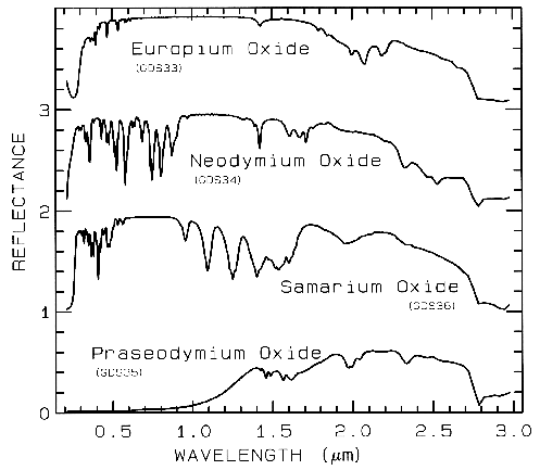 Figure 8a.
Figure 8a. Reflectance spectra of rare-earth
oxides. These absorptions are due to crystal-field
transitions involving deep-lying electrons of the
rare-earth element and do not shift when the
rare-earth ion is in another mineral. Each
spectrum is offset by 1.0 units for clarity. Spectra from
Clark et al. (1993b).
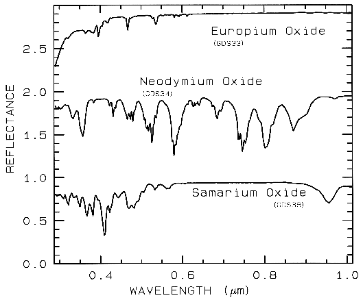 Figure 8b.
Figure 8b. Same as Figure 8a, except showing
absorptions in the visible region. Spectra are
offset 1.0 units for clarity. Spectral resolution
is about 1 nm, critically sampled.
3.1.2 Charge Transfer Absorptions.. Absorption bands can also be caused by charge transfers, or inter-element transitions where the absorption of a photon causes an electron to move between ions or between ions and ligands. The transition can also occur between the same metal in different valence states, such as between Fe2+ and Fe3+. In general, absorption bands caused by charge transfers are diagnostic of mineralogy. Their strengths are typically hundreds to thousands of times stronger than crystal field transitions. The band centers usually occur in the ultraviolet with the wings of the absorption extending into the visible. Charge transfer absorptions are the main cause of the red color of iron oxides and hydroxides (Figure 7a). Morris et al. (1985) studied the details of sub-micron iron oxides where it was found that the absorption bands rapidly decrease in intensity. This occurs because of the increased surface to volume ratio at small grain size results in a greater proportion of grain boundaries where crystal field effects are different, resulting in lower magnetic coupling and reduced absorption strength. Other iron oxides probably show similar effects. Reflectance spectra of iron oxides have such strong absorption bands that the shape changes significantly with grain size. This will be discussed later in this chapter and is also illustrated in Figure 27. Small shifts in absorption band position are also observed due to substitution of other elements, like aluminum for iron in hematite (e.g. Morris et al., 1985 and references therein) but more work needs to be done to fully understand the effects.
3.1.3 Conduction Bands..
In some
minerals, there are two energy levels in which
electrons may reside: a higher level called the
"conduction band," where electrons move freely
throughout the lattice, and a lower energy
region called the "valence band," where
electrons are attached to individual atoms. The
difference between the energy levels is called
the band gap. The band gap is typically small
or non-existent in metals, and very large in
dielectrics. In semiconductors, the band gap
corresponds to the energy of visible to
near-infrared wavelength photons and the
spectrum in these cases is approximately a step
function. The yellow color of sulfur is caused
by such a band gap. The minerals cinnabar
(HgS) and Sulfur (S) have spectra showing the
band gap in the visible (Figure 9).
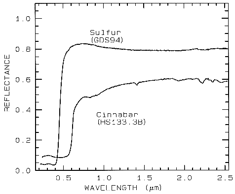 Figure 9.
Figure 9. Reflectance spectra of
Sulfur, S, (top) and cinnabar, HgS, (bottom) showing conduction
bands in the visible (from Clark et al., 1993b).
3.1.4 Color Centers.. A few minerals show color due to absorption by "color centers." A color center is caused by irradiation (e.g. by solar UV radiation) of an imperfect crystal. Crystals in nature have lattice defects that disturb the periodicity of the crystal. For example, defects might be caused by impurities. These defects can produce discrete energy levels and electrons can become bound to them. The movement of an electron into the defect requires photon energy. The yellow, purple and blue colors of fluorite are caused by color centers. See Hunt (1977) and references therein for more details.
More detailed discussions of electronic processes can be found in the review paper by Hunt (1977), Gaffey et al. (1993) and the book by Burns (1993). A summary diagram of the causes of absorption bands is shown in Figure 13.
The bonds in a molecule or crystal lattice are like springs with attached weights: the whole system can vibrate. The frequency of vibration depends on the strength of each spring (the bond in a molecule) and their masses (the mass of each element in a molecule). For a molecule with N atoms, there are 3N-6 normal modes of vibrations called fundamentals. Each vibration can also occur at roughly multiples of the original fundamental frequency. The additional vibrations are called overtones when they involve multiples of a single fundamental mode, and combinations when they involve different modes of vibrations.
A vibrational absorption will be seen in the infrared spectrum only if the molecule responsible shows a dipole moment (it is said to be infrared active). A symmetric molecule, like N2 is not normally infrared active unless it is distorted (for example, when under high pressure). Vibrations from two or more modes can occur at the same frequency, and because they can't be distinguished, are said to be degenerate. An isolated molecule with degenerate modes may show the modes at slightly different frequencies in a crystal because of the non-symmetric influences of the crystal field.
A free molecule can rotate and move translationally, but even in a solid partial rotation and slight translation can occur. These motions are called lattice modes and typically occur at very low energies (longer mid-infrared wavelengths), beyond about 20 µm.
Traditionally, the frequencies of
fundamental vibrations are labeled with the
greek letter nu (v) and a subscript (Herzberg, 1945). If a
molecule has vibration fundamentals v1,
v2, v3,
then it can have overtones at approximately 2v1,
3v1, 2v2
and combinations at approximately
v1+v2,
v2+v3,
v1+v2+v3,
and so on. These
examples used summations of modes, but
subtractions are also possible (e.g.
v1+v3-v2).
Each higher overtone or combination is
typically 30 to 100 times weaker than the last.
Consequently, the spectrum of a mineral can be
quite complex. In reflectance spectroscopy,
these weak absorptions can be measured easily
and diagnostic information routinely gained
from 2nd and 3rd overtones and combinations
(e.g. Figures 5b, 6b, 7b, 10, 11, 12).
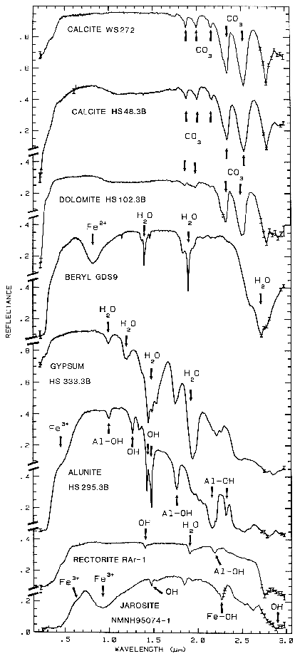 Figure 10a.
Figure 10a. Reflectance spectra of calcite,
dolomite, beryl, gypsum, alunite, rectorite, and jarosite
showing vibrational bands due to OH, CO3
and H2O, from Clark et al., 1990a).
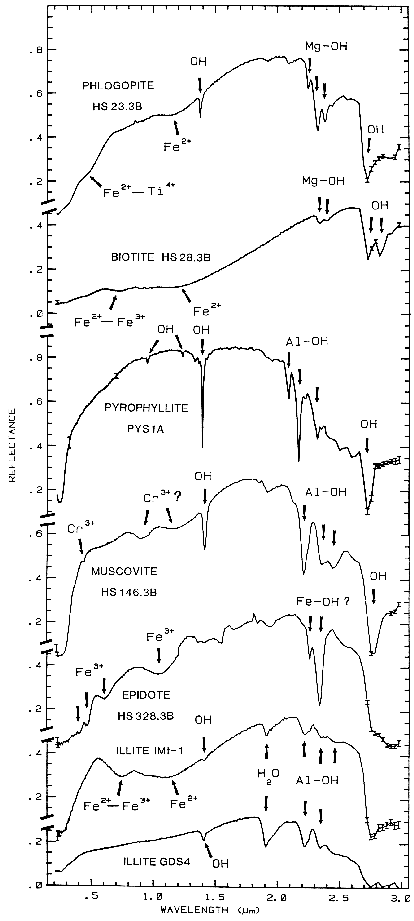 Figure 10b.
Figure 10b. Reflectance spectra of phlogopite,
biotite, pyrophyllite, muscovite, epidote, and illite
showing vibrational bands due to OH and H2O,
from Clark et al., 1990a).
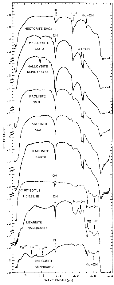 Figure 10c.
Figure 10c. Reflectance spectra of hectorite,
halloysite, kaolinite, chrysotile, lizardite, and
antigorite showing vibrational bands due to OH (from
Clark et al., 1990a). Figure 17 shows an
expanded view of the 1.4-µm region for
chrysotile, lizardite, and antigorite.
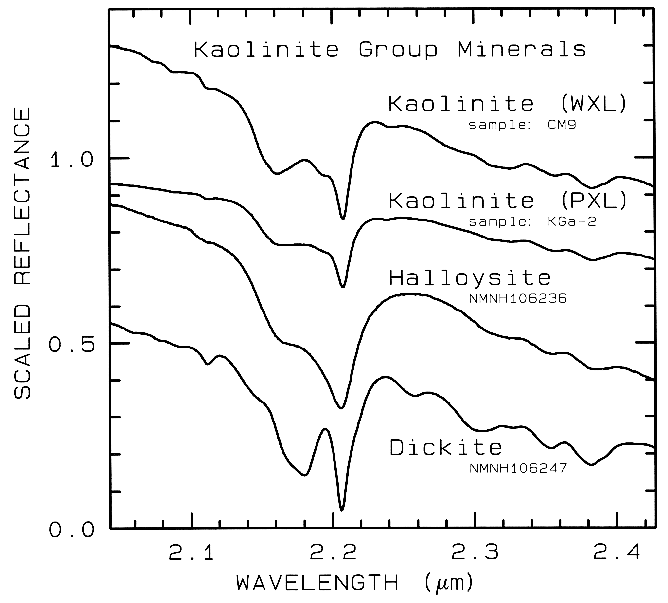
Figure 10d. Subtle spectral differences in the
kaolinite group minerals near 2.2-µm. Kaolinite
CM9 is well crystallized (WXL) while KGa-2 is
poorly crystallized (PXL). Spectral bandwidth
is 1.9 nm and sampling is 0.95 nm. Each
spectrum was scaled to 0.7 at 2.1 µm then offset up or
down so that the curves to not overlap. Original
reflectances were between 0.5 and 0.8.
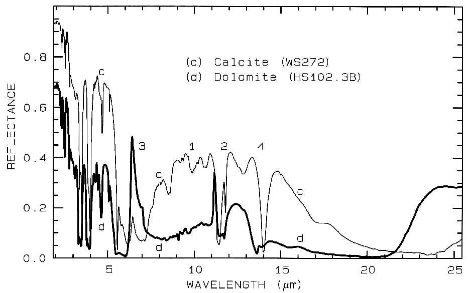
Figure 11. Comparison of calcite (CaCO3)
and dolomite (CaMg(CO3)2) spectra in the mid-infrared
showing small band shifts due to the change in composition
between the two minerals. The level
change (calcite higher in reflectance than dolomite) is
because the calcite has a smaller grain size.
The numbers indicate the fundamental stretching
positions of v1 v2, v3,
and v4. The v1 stretch is
infrared innactive, but may be weakly present in
carbonates. The v3 fundamental is so strong,
only a reflection peak is seen in these spectra.
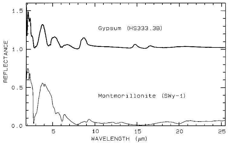
Figure 12 Mid-IR spectra of gypsum,
CaSO42H2O. (top) and montmorillonite,
(Al,Mg)8(Si4O10)3(OH)1012H2O,
(bottom). The gypsum curve is offset upward 1.0 units for
clarity. Both samples have very low reflectance because
of the water content of the samples.
Water is a strong infrared absorber. The montmorillonite
also has a small grain size, which also
tends to produce low mid-infrared reflectance because of
the strong absorption in the mid-infrared.
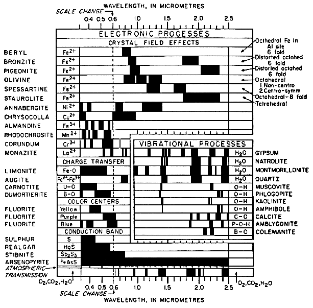
Figure 13a. Spectral signature diagram (from
Hunt, 1977). The widths of the black bars indicate
the relative widths of absorption bands.
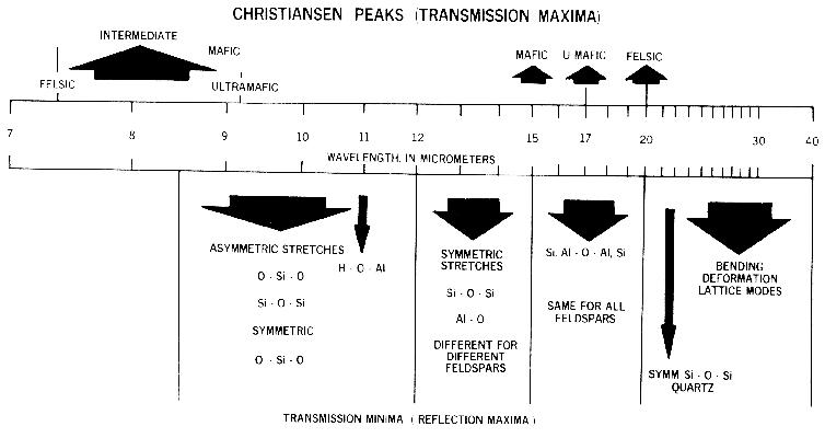
Figure 13b. Illustration of the locations and
causes of absorptions in mid-infrared spectra of
silicates, from Hunt (1982).
Lattice modes are sometimes denoted by vT and vR and also couple with other fundamentals, resulting in finer structure seen in some spectra. The causes of vibrational absorptions in mid-IR spectra are summarized in Figure 13b from Hunt (1982).
Mid-infrared reflectance spectra of quartz are shown in Figure 4b. The strong 9-µm Si-O-Si asymmetric stretch fundamental is obvious from the reflection maximum. The O-Si-O bending mode occurs near 25 µm and is the second strongest absorption. The absorption between 12 and 13 µm is the Si-O-Si symmetric stretch fundamental.
Olivine spectra in the mid-infrared are shown in Figure 5b. When Mg is present, a strong absorption appears near 23 µm, perhaps seen in the Fo 91 spectrum. The Si-O-Si asymmetric stretch fundamental occurs near 11 µm, and a weaker symmetric absorption occurs near 12 µm. The absorptions shift with composition as shown in Figure 5b, and discussed in more detail in Farmer (1974, pp. 288-290).
Pyroxene mid-infrared spectra are shown in Figure 6b. The Si-O fundamentals are at similar to other silicates, as indicated in Figure 13b. Grain size effects will be discussed below in section 6.2 and illustrated in Figure 21.
Iron oxide and iron hydroxide mid-infrared spectra are shown in Figure 7b. Because iron is more massive than silicon, Fe-O fundamentals will be at longer wavelengths than Si-O stretching modes. Hematite, Fe2O3, has 3 strong stretching modes between 16 and 30 µm. Because iron oxides and hydroxides tend to be fine grained, typically less than the wavelength of mid-infrared photons, and because of the strong absorption in the mid-infrared, iron oxides tend to be dark in reflectance showing few features beyond about 12 µm. The hematite in Figure 7b has a small amount of water as evidenced by the 3-µm absorption, and a moderate amount of organics as seen by the C-H stretch fundamental near 3.4 µm. The goethite, FeOOH, having hydroxyl has a strong 3-µm absorption. The olivines (Figure 5) and pyroxenes (Figure 6) also show small amounts of water in the sample as seen by the 3-µm absorptions in their spectra.
3.2.1 Water and Hydroxyl. Water and OH (hydroxyl) produce particularly diagnostic absorptions in minerals. The water molecule (H2O) has N=3, so there are 3N-6=3 fundamental vibrations. In the isolated molecule (vapor phase) they occur at 2.738 µm (v1, symmetric OH stretch), 6.270 µm (v2, H-O-H bend), and 2.663 µm (v3, asymmetric OH stretch). In liquid water, the frequencies shift due to hydrogen bonding: v1=3.106 µm, v2=6.079 µm, and v3=2.903 µm.
The overtones of water are seen in reflectance spectra of H2O-bearing minerals (Figure 10). The first overtones of the OH stretches occur at about 1.4 µm and the combinations of the H-O-H bend with the OH stretches are found near 1.9 µm. Thus, a mineral whose spectrum has a 1.9-µm absorption band contains water (e.g. hectorite and halloysite in Figure 10c), but a spectrum that has a 1.4-µm band but no 1.9-µm band indicates that only hydroxyl is present (e.g. kaolinite in Figure 10c has only a small amount of water because of the weak 1.9-µm absorption but a large amount of OH). The hydroxyl ion has only one stretching mode and its wavelength position is dependent on the ion to which it is attached. In spectra of OH-bearing minerals, the absorption is typically near 2.7 to 2.8 µm, but can occur anywhere in the range from about 2.67 µm to 3.45 µm (e.g. see Clark et al., 1990 and references therein). The OH commonly occurs in multiple crystallographic sites of a specific mineral and is typically attached to metal ions. Thus, there may be more than one OH feature. The metal-OH bend occurs near 10 µm (usually superimposed on the stronger Si-O fundamental in silicates). The combination metal-OH bend plus OH stretch occurs near 2.2 to 2.3 µm and is very diagnostic of mineralogy (e.g. see Clark et al., 1990 and references therein).
3.2.2 Carbonates. Carbonates also show diagnostic vibrational absorption bands (Figure 10a, 11). The observed absorptions are due to the planar CO3-2 ion. There are four vibrational modes in the free CO3-2 ion: the symmetric stretch, v1: 1063 cm-1 (9.407 µm); the out-of-plane bend, v2: 879 cm-1 (11.4 µm); the asymmetric stretch, v3: 1415 cm-1 (7.067 µm); and the in-plane bend, v4: 680 cm-1 (14.7 µm). The v1 band is not infrared active in minerals. There are actually six modes in the CO3-2 ion, but 2 are degenerate with the v3 and 4 modes. In carbonate minerals, the v3 and v4 bands often appear as a doublet. The doubling has been explained in terms of the lifting of the degeneracy (e.g. see White, 1974) due to mineral structure and anion site.
Combination and overtone bands of the CO3 fundamentals occur in the near IR. The two strongest are v1 + 2v3 at 2.50-2.55µm (4000-3900 cm-1), and 3v3 at 2.30-2.35 µm (4350-4250 cm-1; e.g. Figure 10a). Three weaker bands occur near 2.12-2.16 µm (v1 + 2v3 + v4 or 3v1 + 2v4; 4720-4630 cm-1), 1.97-2.00 µm (2v1 + 2v3; 5080-5000 cm-1), and 1.85-1.87 µm (v1 + 3v3; 5400-5350 cm-1; e.g. Figure 10a) (e.g. Hunt and Salisbury, 1971). The band positions in carbonates vary with composition (Hunt and Salisbury, 1971; Gaffey, 1986, Gaffey et al., 1993). An example of such a band shift is seen in Figures 10a, 11 and, in more detail, Figure 24a showing the shift in absorption position from calcite to dolomite.
3.2.3 Other Minerals. Phosphates, borates, arsenates, and vanadates also have diagnostic vibrational spectra. Space precludes inclusion of spectra here. See Hunt et al., (1972), and Clark et al., (1993b) for visual to near-infrared spectra. In general, the primary absorptions (e.g. P-O stretch) occurs at mid-infrared wavelengths. However, many of these minerals contain OH or H20 and have absorptions in the near-infrared.
In the mid-infrared, minerals with H2O, or those that are fine grained, like clays, have very low reflectance, and show only weak spectral structure (e.g. Figure 12). Therefore, in emittance, spectral features will also be weak and thus difficult to detect. Grain size effects will be discussed further below.
Typical spectra of minerals with vibrational bands are shown in Figure 4b, 5b, 6b, 7b, and 10. See Hunt and Salisbury (1970), Hunt and Salisbury (1971), Hunt et al. (1971a,b, 1972, 1973), Hunt (1979), Farmer (1974), Gaffey (1986, 1987), Gaffey et al., 1993, Clark et al. (1990a), King and Clark (1989a), Swayze and Clark (1990), Mustard (1992) and Salisbury (1993), for more details. A summary of absorption band positions and causes is shown in Figure 13a, b.
4. SPECTRA OF MISCELLANEOUS MINERALS AND MATERIALS
Organic materials are found all over the
Earth, and in the solar system. Organics can be
important compounds in some environmental
problems. The C-H stretch fundamental occurs
near 3.4 µm, (e.g. Figure 14a) the first overtone
is near 1.7 µm, and a combination band near
2.3 µm (Figure 14b). The combinations near
2.3 µm can sometimes be confused with OH
and carbonate absorptions in minerals (e.g.
Figure 10), especially at low spectral resolution.
Further discussions and references can be found
in Chapter XX of the Manual of Remote Sensing.
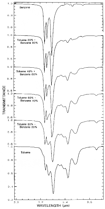 Figure 14a.
Figure 14a. Transmittance spectra of organics
and mixtures showing the complex absorptions in
the CH-stretch fundamental spectral region.
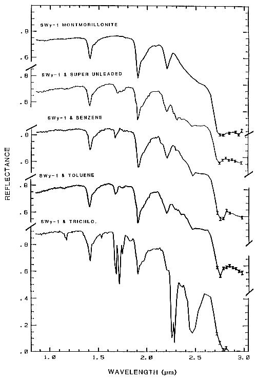 Figure 14b.
Figure 14b. Reflectance spectra of montmorillonite,
and montmorillonite mixed with super
unleaded gasoline, benzene, toluene, and trichlorethylene.
Montmorillonite has an absorption
feature at 2.2 µm, whereas the organics have a
CH combination band near 2.3 µm. The first
overtone of the CH stretch can be seen at 1.7 microns,
and the second overtone near 1.15 µm.
From King and Clark (1989b).
Just like water in minerals shows diagnostic absorption bands, ice (crystalline H2O) which is formally a mineral, also shows strong absorption bands. In the planetary literature it is referred as water ice, so as not to confuse it with other ices. Spectra of solid H2O, CO2, and CH4 are shown in Figure 15. The spectral features in Figure 15 are all due to vibrational combinations and overtones, whose fundamentals have previously been discussed in general. Note the H2O spectra show broad absorptions compared to the others. The reason is that while ice is normally a hexagonal structure, the hydrogen bonds are orientationally disordered (e.g. Hobbs, 1974), and the disorder broadens the absorptions. There are many ices in the solar system (e.g. see reviews by Clark et al., 1986, and Cruikshank et al., 1985).
Ice, being ubiquitous in the solar system
is found mixed with other minerals, on the
Earth, as well as elsewhere in the solar system
(e.g. Clark et al., 1986). The spectral properties
if ice and ice-mineral mixtures have been
studied by Clark (1981a, b), Clark and Lucey
(1984), Lucey and Clark (1985) and references
therein.
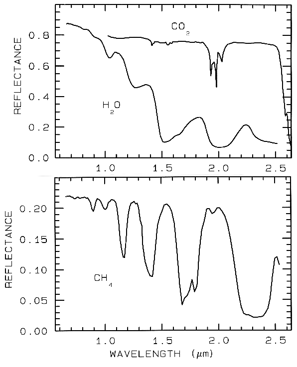 Figure 15.
Figure 15. Reflectance spectra of solid carbon
dioxide, CO2, methane, CH4, and water, H2O,
from Clark et al. (1986).
Spectra of vegetation come in two
general forms: green and wet (photosynthetic),
and dry non-photosynthetic but there is a
seemingly continuous range between these two
end members. The spectra of these two forms
are compared to a soil spectrum in Figure 16.
Because all plants are made of the same basic
components, their spectra appear generally
similar. However, in the spectral analysis
section we will see methods for distinguishing
subtle spectral details. The near-infrared
spectra of green vegetation are dominated by
liquid water vibrational absorptions. The water
bands are shifted to slightly shorter wavelengths
than in liquid water, due to hydrogen bonding.
The absorption in the visible is due to
chlorophyll, and is discussed in more detail in
Chapter XX of Manual of Remote Sensing. The dry non-photosynthetic
vegetation spectrum shows absorptions due to
cellulose, lignin, and nitrogen. Some of these
absorptions can be confused with mineral
absorptions, unless a careful spectral analysis is
done.
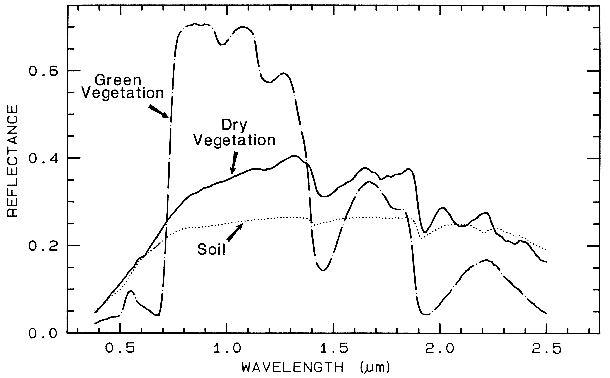
Figure 16. Reflectance spectra of photosynthetic (green) vegetation, non-photosynthetic (dry)
vegetation, and a soil. The green vegetation has absorptions short of 1 µm due to chlorophyll.
Those at wavelengths greater than 0.9 µm are dominated by liquid water. The dry vegetation
shows absorptions dominated by cellulose, but also lignin and nitrogen. These absorptions must
also be present in the green vegetation, but can be detected only weakly in the presence the
stronger water bands. The soil spectrum shows a weak signature at 2.2 µm due to
montmorillonite.
5. THE SENSITIVITY OF ABSORPTION BANDS TO CRYSTAL STRUCTURE AND CHEMISTRY
Reflectance spectroscopy shows a wealth of information about mineralogy. Why, then, is spectroscopy not a more widely used technique? In many cases spectroscopy is very sensitive to subtle changes in crystal structure or chemistry. This has resulted in confusion in the past over cause and effect. More recently, this sensitivity has been recognized as a powerful means of studying the structure and composition of minerals. Additional problems occur with reflectance spectra due to scattering and will be discussed below.
Because spectroscopy is sensitive to so many processes, the spectra can be very complex and there is still much to learn. However, it is because of this sensitivity that spectroscopy has great potential as a diagnostic tool. In fact for some materials, spectroscopy is an excellent tool not only for detecting certain chemistries, but also at abundance levels unmatched by other tools. For example, each layer of a layered silicate absorbs radiation almost independently from its neighbors. The absorption of photons does not depend on the longer range crystallographic order as is required to give distinctive X-ray diffraction patterns. Thus, many processes, for example clay dehydroxylation, are detectable with spectroscopy before other methods (e.g. see Farmer, 1974, page 355). Spectroscopy is more sensitive to the presence of clays, iron oxides, iron hydroxides, quartz, and other minerals with strong absorption bands at levels significantly lower than other methods such as X-ray diffraction (e.g. Farmer, 1974, see page 355). Here, a few examples of the possibilities will be shown.
5.1 Example: Pyroxenes. The iron bands near 1 and 2 µm shift with pyroxene composition as shown in Figure 6a, c. This series has been calibrated by Adams (1975), Cloutis et al. (1986), and Cloutis and Gaffey (1991). The olivine 1-µm band also shifts with composition (Figure 5a), although more subtly than with pyroxenes, and the shift has been calibrated by King and Ridley (1987). Note also the shifts, seen as positions of absorption minima and reflectance maxima, in the mid-infrared with different compositions in Figures 5b and 6b.
5.2 OH Examples.
The sharper
OH-related absorption bands allow smaller
band shifts to be measured. These bands can be
so sensitive that it is possible to distinguish
between the isochemical end-members of the
Mg-rich serpentine group, chrysotile, antigorite,
and lizardite (King and Clark, 1989a, and
Figure 17). The Fe:Fe+Mg ratio can be
estimated from reflectance spectra of minerals
with brucite-like structure (Clark et al., 1990a,
Mustard, 1992, and Figure 17). Mustard
(1992) calibrated changes in the 1.4-µm and
2.3-µm absorptions in the tremolite-actinolite
solid solution series; example spectra of the 1.4-µm absorptions are shown in Figure 17.
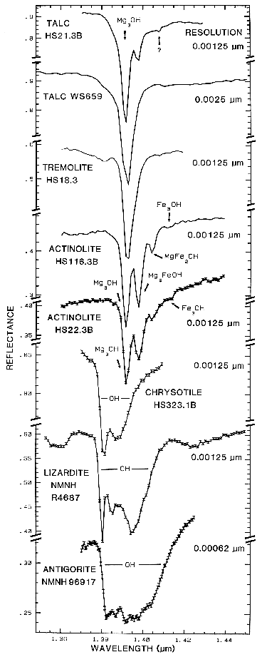 Figure 17.
Figure 17. High spectral resolution reflectance spectra of the first overtone of OH in talc,
tremolite, actinolite, crysotile, lizardite, and antigorite. The three sharp absorption bands in talc,
tremolite and actinolite are caused by Mg and Fe ions associated with the hydroxyls, causing small
band shifts. The Fe:Fe+Mg ratio can be estimated. In chrysotile, lizardite and antigorite, the
absorptions change with small structural differences even though the composition is constant (from
Clark et al., 1990a).
The structure of the 2.2-µm Al-OH band has been shown to be diagnostic of disorder in kaolinite-dickite mixtures (Crowley et al., 1988) and the degree of kaolinite crystallinity (Clark et al., 1990a), which is illustrated in Figures 10c, d.
The strong and sharp OH features have proven particularly diagnostic of clay mineralogy, perhaps better than with X-ray diffraction (XRD) analysis (like any method, spectroscopy has advantages in some areas and XRD in others). For example, it appears easy to distinguish kaolinite from halloysite with spectroscopy (e.g. Clark et al., 1990a), as shown in Figures 10c, d. Montmorillonite is easily distinguished from illite or muscovite (e.g. Clark et al., 1990a) whereas XRD analysis combines them into the general term smectites.
5.3 Al in Muscovite.
More recently,
subtle shifts have been found in muscovite
series with aluminum composition. (e.g. Post
and Noble, 1993; Duke, 1995; Swayze, 1997).
As elements substitute for aluminum in the
crystal structure, the crystal becomes slightly
distorted relative to no substitutions. This
causes slight changes in Al-O-H bond lengths
and thus shifts absorption band position.
Example shifts with composition are shown in
Figure 18. In this case, the shift of the 2.2-µm
absorption appears continuous with
composition, compared to the growth of
specific absorptions as in the tremolite-actinolite series shown in Figure 17. It is likely
that all muscovite-group minerals show similar
behavior, and illites may also.
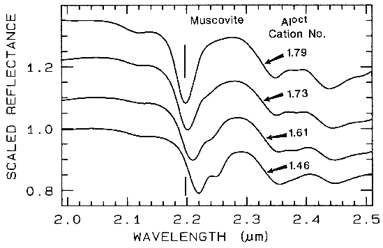 Figure 18.
Figure 18. Reflectance spectra of muscovite
showing band shifts due to changing aluminum
composition, from Swayze (1997).
5.4 Discussion. Reflectance spectroscopy can be used without sample preparation, and it is non-destructive. This makes mapping of exposed minerals from aircraft possible, including detailed clay mineralogy (e.g. Clark et al., 1993a). Visual and near-infrared spectroscopy, on the other hand, is insensitive to some minerals which do not have absorptions in this wavelength region. For example, quartz has no diagnostic spectral features in the visible and near-infrared; in fact it is used as optical components in many telescopes and prisms. Quartz must be detected at its fundamental Si-O stretching region near 10 µm., as shown in Figure 4b.
Now that we have explored the causes of absorption features in minerals, we will explore how those features get modified.
Scattering is the process that makes reflectance spectroscopy possible: photons enter a surface, are scattered one or more times, and while some are absorbed, others are scattered from the surface so that we may see and detect them. Scattering can also be thought of as scrambling information. The information is made more complex, and because scattering is a non-linear process, recovery of quantitative information is more difficult.
Consider the simple Beers Law in equation 1b. In transmission, light passes through a slab of material. There is little or no scattering (none in the ideal case; but there are always internal reflections from the surfaces of the medium). Analysis is relatively simple. Reflectance of a particulate surface, however, is much more complex and the optical path of photons is a random walk. At each grain the photons encounter, a certain percentage are absorbed. If the grain is bright, like a quartz grain at visible wavelengths, most photons are scattered and the random walk process can go on for hundreds of encounters. If the grains are dark, like magnetite, the majority of photons will be absorbed at each encounter and essentially all photons will be absorbed in only a few encounters. The random walk process, scattering and the mean depth of photon penetration are discussed in Clark and Roush (1984).
The random walk process of photons scattering in a particulate surface also enhances weak features not normally seen in transmittance, further increasing reflectance spectroscopy as a diagnostic tool. Consider two absorption bands of different strengths, such as a fundamental and an overtone. The stronger absorption will penetrate less into the surface, encountering fewer grains because the photons are absorbed. At the wavelengths of the weaker absorption, less photons are absorbed with each encounter with a grain, so the random walk process goes further, increasing the average photon path length. The greater path length will result in more absorption, thus strengthening the weak absorption in a reflectance spectrum.
The real world (and for that matter, the universe) is a complex mixture of materials, at just about any scale we view it. In general, there are 4 types of mixtures:
1) Linear Mixture. The materials in the field of view are optically separated so there is no multiple scattering between components. The combined signal is simply the sum of the fractional area times the spectrum of each component. This is also called areal mixture.
2) Intimate Mixture. An intimate mixture occurs when different materials are in intimate contact in a scattering surface, such as the mineral grains in a soil or rock. Depending on the optical properties of each component, the resulting signal is a highly non-linear combination of the end-member spectra.
3) Coatings. Coatings occur when one material coats another. Each coating is a scattering/transmitting layer whose optical thickness varies with material properties and wavelength.
4) Molecular Mixtures. Molecular mixtures occur on a molecular level, such as two liquids, or a liquid and a solid mixed together. Examples: water adsorbed onto a mineral; gasoline spilled onto a soil. The close contact of the mixture components can cause band shifts in the adsorbate, such as the interlayer water in montmorillonite, or the water in plants.
An example mixture comparison is
shown in Figure 19 for alunite and jarosite.
Note in the intimate mixture how the jarosite
dominates and the 0.4 to 1.3-µm region. The
reason is because in an intimate mixture, the
darker material dominates because photons are
absorbed when they encounter a dark grain. In
the areal mixture, the brighter material
dominates.
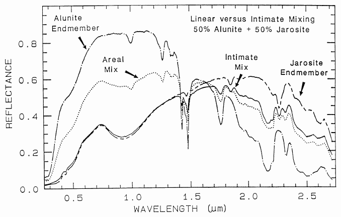
Figure caption foes here
Figure 19. Reflectance spectra of alunite, jarosite and mixtures of the two. Two mixture types
are shown: intimate and areal. In the intimate mixture, the darker of the two spectral components
tends to dominate, and in and areal mixture, the brighter component dominates. The areal mixture
is a strictly linear combination and was computed from the end-members, whereas the intimate
mixture is non-linear and the spectrum of the physical mixture was measured in the laboratory.
The jarosite dominates the 0.3-1.4 µm wavelength region in the intimate mixture because of the
strong absorption in jarosite at those wavelengths and because the jarosite is finer grained than the
alunite and tends to coat the larger alunite grains.
In a mixture of light and dark grains
(e.g. quartz and magnetite) the photons have
such a high probability of encountering a dark
grain that a few percent of dark grains can
drastically reduce the reflectance, much more
than their weight fraction. The effect is
illustrated in Figure 20 with spectra of samples
having various proportions of charcoal grains
mixed with montmorillonite.
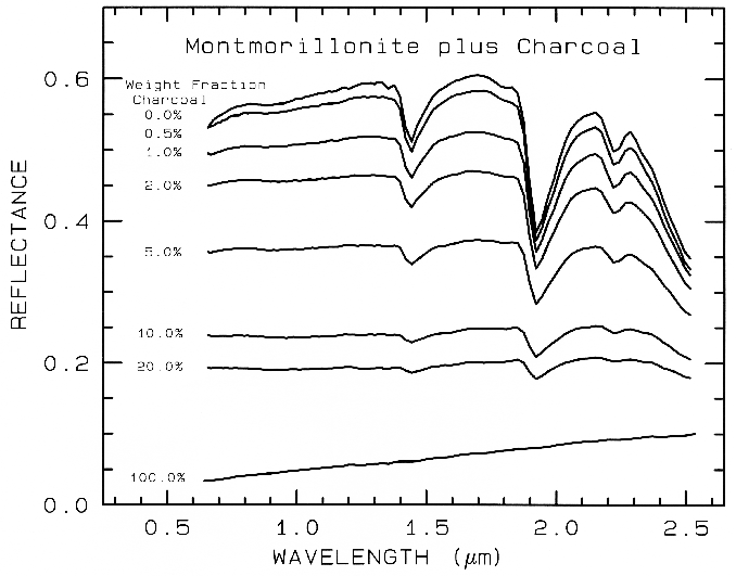
Figure 20. Reflectance spectra of intimate mixtures of montmorillonite and charcoal illustrates
the non-linear aspect of reflectance spectra of mixtures, from Clark (1983). The darkest substance
dominates at a given wavelength.
The amount of light scattered and
absorbed by a grain is dependent on grain size
(e.g. Hapke, 1993; Clark and Roush, 1984; and
Figures 21 and 22). A larger grain has a greater
internal path where photons may be absorbed
according to Beers Law. It is the reflection
from the surfaces and internal imperfections
that control scattering. In a smaller grain there
are proportionally more surface reflections
compared to internal photon path lengths, or in
other words, the surface-to-volume ratio is a
function of grain size. If multiple scattering
dominates, as is usually the case in the visible
and near- infrared, the reflectance decreases as
the grain size increases, as shown in the
pyroxene visible to near-infrared spectra in
Figure 21a. However, in the mid-infrared,
where absorption coefficients are much higher
and the index of refraction varies strongly at the
Christensen frequencies, first surface reflection
is a larger or even dominant component of the
scattered signal. In these cases, the grain size
effects are much more complex, even reversing
trends commonly seen at shorter wavelengths
(e.g. Figure 21b).
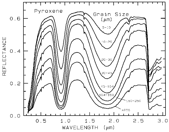
Figure 21a. Reflectance Spectra of pyroxene as a function of grain size. As the grain size
becomes larger, more light is absorbed and the reflectance drops (from Clark et al., 1993b).
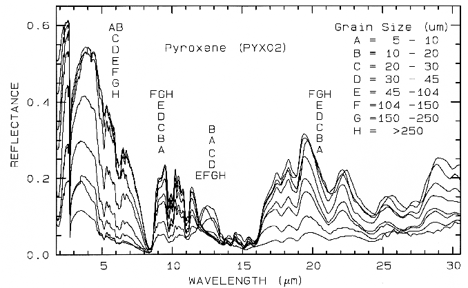
Figure 21b. Same series as in Figure 21a, but for the mid-IR. The position of letter identifiers
indicates the relative position of the spectra at the various wavelengths. Note the reversal in the
trends at some wavelengths and not others. Grain size effects on the shapes of spectral features
in the mid-IR can be quite large.
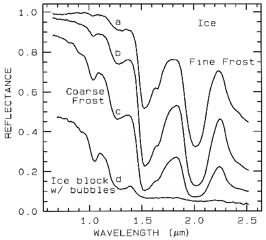
Figure 22a. The near-infrared spectral reflectance of A) a fine grained (~50 µm) water frost, B)
medium grained (~200 µm) frost, C) coarse grained (400-2000 µm) frost and D) an ice block
containing abundant microbubbles. The larger the effective grain size, the greater the mean photon
path that photons travel in the ice, and the deeper the absorptions become. Curve D is very low in
reflectance because of the large path length in ice. The ice temperatures for these spectra are 112-140 K. From Clark et al. (1986).
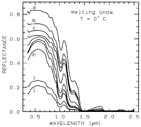 Figure 22b.
Figure 22b. A series of reflectance spectra of melting snow. The top curve (a) is at 0o C and has
only a small amount of liquid water, whereas the lowest spectrum (j) is of a puddle of about 3 cm
of water on top of the snow. Note in the top spectrum, there is no 1.65-µm band as in the ice
spectra in figure 22a because of the higher temperature.. The 1.65-µm feature is temperature
dependent and decreases in strength with increasing temperature (see Clark, 1981a and references
therein). Note the increasing absorption at about 0.75 µm and in the short side of the 1-µm ice
band, as more liquid water forms. The liquid water becomes spectrally detectable at about
spectrum e, when the UV absorption increases. Spectra from Clark, King and Swayze, in
preparation.
Back to Contents
6.3 The Continuum and Band Depth.
Absorptions in a spectrum have two components: continuum and individual features. The continuum is the "background absorption" onto which other absorption features are superimposed (e.g. see Clark and Roush, 1984). It may be due to the wing of a larger absorption feature. For example, in the pyroxene spectra in Figure 21a, the weak feature at 2.3 µm is due to a trace amount of tremolite in the sample and the absorption is superimposed on the broader 2-µm pyroxene band. The broader pyroxene absorption is the continuum to the narrow 2.3-µm feature. The pyroxene 1.0-µm band is superimposed on the wing of a stronger absorption centered in the ultraviolet.
The depth of an absorption band, D, is usually defined relative to the continuum, Rc:
D = 1 - Rb / Rc (2)
where Rb is the reflectance at the band bottom, and Rc is the reflectance of the continuum at the same wavelength as Rb (Clark and Roush, 1984).
The depth of an absorption is related to the abundance of the absorber and the grain size of the material. Consider a particulate surface with two minerals, one whose spectrum has an absorption band. As the abundance of the second mineral is increased, the band depth, D, of the absorption in the first mineral will decrease. Next consider the visual and near-infrared reflectance spectrum of a pure powdered mineral. As the grain size is increased from a small value, the absorption-band depth, D, will first increase, reach a maximum, and then decrease. This can be seen with the pyroxene spectra in Figure 21a and more so in the ice spectra in Figure 22. If the particle size were made larger and larger, the reflectance spectrum would eventually consist only of first surface reflection, like at most wavelengths beyond 1.45 µm in the ice spectra in Figure 22. The reflectance can never go to zero because of this reflection, unless the index of refraction of the material is 1.0. These concepts, called "band saturation" are explored further in Clark and Lucey (1984) and Lucey and Clark (1985).
A sloping continuum causes an apparent
shift in the reflectance minimum, as shown in
Figure 23. Continuaa can be thought of as an
additive effect of optical constants, but in
reflectance spectra, scattering and Beers Law
make the effects non-linearly multiplicative (see
Clark and Roush, 1984 for more details). So
the continuum should be removed by division,
whether you are working in reflectance or
emittance. The continuum should be removed
by subtraction only when working with
absorption coefficients. In a spectrum with a
sloping continuum, correction removes the
effect of shifts in the local reflectance minimum
(Figure 23). Note your perception of spectrum
E versus A in Figure 23. The spectral features
do not appear to be the same, but if you remove
the continuum, it is obvious they are the same
(Figure 23, top).
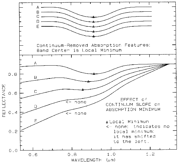
Figure 23. Illustration of continua and continuum removal. In the lower set of curves, the local
minimum in the curve shifts to shorter wavelengths with increasing slope. removal of the
continuum by division isolates the spectral features so they may be compared (top). The top set
of curves are offset for clarity. In the continuum-removed spectra, we can see there is no real shift
in the absorption-band center.
Back to Contents
6.4 Continuum-Removed Spectral
Feature Comparison.
The continuum-removal process isolates
spectral features and puts them on a level
playing field so they may be intercompared.
Continuum removal and feature comparison, is
in this author's opinion, the key to successful
spectral identification. For example, compare
the spectra of calcite (CaCO3) and dolomite
(CaMg(CO3)2) in Figure 10a. If we isolate the
spectral features, remove the continuum, and
scale the band depth (or band area) to be equal,
we can see subtle band shifts and shapes
(Figure 24a). Now compare a harder case:
halloysite and kaolinite (Figure 10c). You
might note that halloysite has a different
absorption feature at 1.9 µm. However, if you
were obtaining the spectrum through the Earth's
atmosphere, you would have virtually no data in
that wavelength region because atmospheric
water absorbs too much of the signal. The
diagnostic feature is the 2.2-µm band. The
continua removed 2.2-µm features for halloysite
and kaolinite are shown in Figure 24b, where
we can see significant differences between the
spectra of the two minerals.
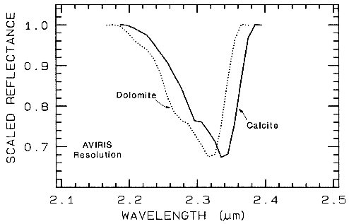 Figure 24a.
Figure 24a. Comparison of calcite and dolomite continuum-removed features. The dolomite
absorption occurs at a shorter wavelength than the calcite absorption.
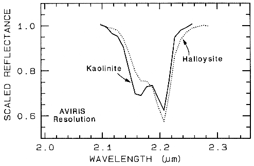 Figure 24b.
Figure 24b. Comparison of kaolinite and halloysite spectral features. Both mineral spectra have
the same band position at 2.2 µm. However, the kaolinite spectrum shows a stronger feature at
2.16 µm than in the halloysite spectrum.
One of the most challenging spectral
features to distinguish between are those in
spectra of various plant species. Figure 25a
shows four plant spectra (the spectra are offset
for clarity). The overall shapes are quite
similar. If we remove the continuum according
to Figure 25b, we see the detailed chlorophyll
absorption spectral variations for these as well
as other plants in Figure 25c. Shape matching
algorithms, like that presented in Clark et al.
(1990b), can distinguish between these spectra
and accurately compare them to spectral
libraries (e.g. see Clark et al., 1993b, Mustard
and Sunshine, Chapter 6).
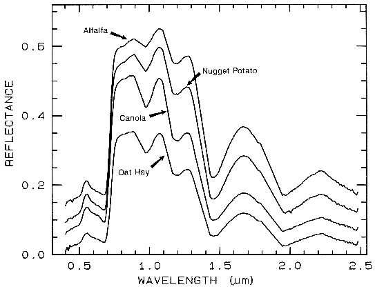 Figure 25a.
Figure caption foes here
Figure 25a. Reflectance spectra of four types of vegetation. Each curve is offset by 0.05
reflectance unit from the one below. From Clark et al. (1995, 1997).
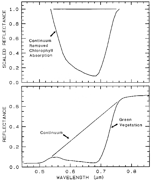 Figure 25b.
Figure 25b. Continuum removal example for a chlorophyll absorption in vegetation.
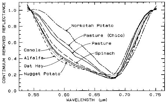
Figure 25c. Continuum-removed chlorophyll absorptions for 8 vegetation types (including the 4
from Figure 25a) showing that the continuum removed features can show subtle spectral
differences. From Clark et al. (1995, 1997).
Back to Contents
6.5 Other Spectral Variability and Rules.
6.5.1 Viewing Geometry.
First, your eye is a crude spectrometer, able to distinguish the spectral properties of materials in a limited wavelength range by the way we interpret color. Pick up any colored object around you. Change the orientation of the local normal on the surface of the object with respect to the angle of incident light, the angle at which you observe it (called the emission or scattering angle), and the angle between the incident and scattered light (the phase angle). As you do this, note any color changes. Unless you chose an unusual material (like a diffraction grating or very shiny object), you will see no significant color change. Plant leaves appear green from any angle, a pile of hematite appears red from any angle. This tells you that the spectral features do not change much with viewing geometry. Your eye/brain combination normalizes intensity variations so that you see the same color, regardless of the actual brightness of the object (the amount of light falling on the surface). The continuum removal does a similar but more sophisticated normalization. The band depth, shape, and position are basically constant with viewing geometry. Band depth will only change with the proportion of specular reflection added to the reflected light. For surfaces (and at wavelengths) where multiple scattering dominates, that change in band depth is minimized.
Back to Contents
6.5.2 Ratioing Spectra.
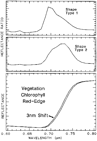 Figure 26.
Figure 26. The ratio of two spectra, one slightly shifted from the other results in a spectral
feature. The two shapes in this example are from different chlorophyll bands. Shifts as small as
0.01 times the full width at half maximum of the spectrometer system produce 1% features in
ratios of strong chlorophyll absorptions. The shape, type 1 profile is from the shifted spectra
shown at the bottom of the figure, while the shape, type 2 is from shallower chlorophyll
absorptions. From Clark et al. (1997).
Back to Contents
6.5.3 Iron Oxide, Hydroxide, Sulfate Complexity.
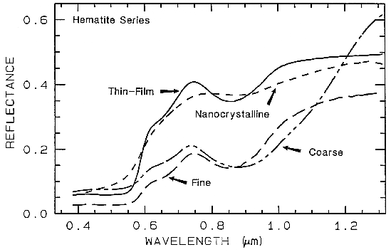 Figure 27a.
Figure 27a. Reflectance spectra of different grain sizes of hematite.
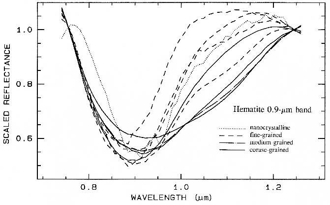
Figure 28a. Spectra of iron oxide, iron hydroxide, and iron sulfate spectra.
There are a whole suite of iron oxides, iron hydroxides, iron sulfates, etc., some only now being discovered, and many amorphous phases, all with similar electronic absorption bands in the visible and near-infrared. A few examples are shown in Figure 28a. Note that hematite has a narrower absorption at a slightly shorter wavelength than goethite. However, a coarse-grained hematite has a broader absorption, approaching the position and width of a fine-grained goethite (or a thin-film goethite).
Jarosite has a narrow absorption near 0.43 µm, but it sometimes appears weak because of the saturated UV absorption. Jarosite, an iron sulfate, has a diagnostic absorption at 2.27 µm due to a combination OH stretch and Fe-OH bend. However, this feature is weaker than the electronic absorptions in the visible and is often masked by clay or alunite (jarosite often occurs in hydrothermal deposits with alunite). The features near 1.475 µm and 1.8 µm are OH related and are commonly seen in sulfate spectra.
Ferrihydrite is an amorphous iron oxide,
and its spectrum appears very similar to the
orange precipitate, an amorphous iron
hydroxide, obtained downstream from the
Summitville, Colorado mine (King et al.,
1995). However, if we remove the continuum
and compare the positions and shapes of the
bands (Figure 28b), we can see they are indeed
different.
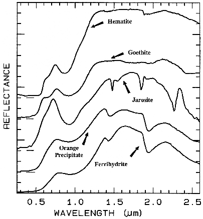 Figure 28a.
Figure 28a. Spectra of iron oxide, iron hydroxide, and iron sulfate spectra.
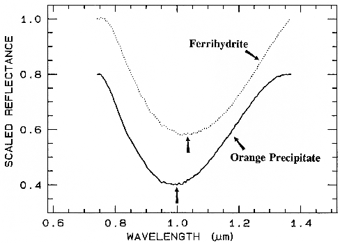 Figure 28b.
Figure 28b. Comparison of the 1-µm continuum-removed-absorption feature of ferrihydrite and
an amorphous iron hydroxide (the orange precipitate from Figure 28a). The spectra are offset for
clarity. Note the shift in the band center between the two spectra despite the similarities in Figure
28a.
As discussed above, there are many iron-bearing minerals and amorphous materials with similar but distinct absorption bands. How many can be distinguished with reflectance spectroscopy is still a matter of research. An even harder question to answer is how many can be distinguished and not be confused with mixtures of other iron-bearing materials. Detailed spectral analysis, including continuum removal to isolate absorption features can certainly improve the success of distinguishing them.
Iron oxides, hydroxides, and sulfates are additional cases where spectroscopy detects at very low levels because of the strong absorption bands in the visible and ultraviolet. In nature, there appear to be many amorphous iron oxides, hydroxides, etc., with equally intense absorptions. Thus, spectroscopy can not only detect them at levels below other methods (e.g. X-ray diffraction), but in the case of amorphous materials detect them when other methods are not sensitive to their presence when they are major fractions of the sample!
Back to Contents
7. QUANTITATIVE UNDERSTANDING: RADIATIVE TRANSFER THEORY.
There have been many attempts over the years to quantify the scattering process. Kubelka-Munk theory was one of the first and still finds uses today (e.g. Wendlandt and Hecht, 1966; Clark and Roush, 1984). A growing popular method in some industries is log (1/R), where R is reflectance, but this is a less robust attempt at quantifying the scattering process than the decades-old Kubelka-Munk theory (Clark and Roush, 1984). The log (1/R) method is usually combined with computing the derivatives of the log (1/R) spectra and doing a correlation analysis to find particular trends. This has popularly become known as Near-Infrared Reflectance Analysis (NIRA). Either method has its uses in controlled situations, but there is a modern, more effective alternative. The limitations of these older methods are due to a poor representation of the scattering process and are discussed in Clark and Roush (1984) and Hapke (1993).
Fortunately, in the early 1980's three independent investigations (Hapke, 1981, Gougen, 1981; and Lumme and Bowell, 1982) provided reasonable solutions to the complex radiative transfer problem as applied to particulate surfaces. These theories provide for non-isotropic scattering of light from particles, shadowing between particles, and first surface reflection from grain surfaces, important processes not considered in earlier theories. One theory, that of Hapke (1981, 1993) also provides for mixtures, and because of its relative simplicity compared to the other two, has become the dominant theory used in the planetary and to some degree the terrestrial remote sensing communities.
Back to Contents
7.1 "Hapke Theory."
r'(w',lambda,µ,g) = [w'/(4pi)][ µ / (µ+µo)] {[1+B(g)]P(g)+H(µ)H(µo)-1} (eqn 3)
where r' is the reflectance at wavelength , µo is the cosine of the angle of incident light, µ is the cosine of the angle of emitted light, g is the phase angle, w' is the average single scattering albedo, B(g) is a backscatter function, P(g) is the average single particle phase function, and H is the Chandrasekhar (1960) H-function for isotropic scatterers. When r' > 0.9 Hapke's approximation of the H-function shows considerable error and equation 3 deviates from measurements (Hapke, 1981). Because of this deviation, a table interpolation subroutine using "exact" values from Chandrasekhar (1960) can be used. The table interpolation is computationally faster than the Hapke approximation and more accurate.
The single scattering albedo is the probability that a photon survives an interaction with a single particle, which includes Fresnel reflection, absorption, scattering, and diffraction due to the presence of an individual grain. Hapke (1981) developed the theory further by deriving a relation between the single scattering albedo, the complex index of refraction, the grain size, and a scattering parameter to describe scattering centers within non-perfect grains. The single scattering albedo of a grain can be found from his equation 24:
w = SE + [(1-SE)(1+SI){r1 + exp[-2(k(k+s))½ d/3]}] / [1 -r1SI + (r1 - SI) exp[-2(k(k+s))½ d/3]] (eqn 4)
where SE and SI are the external and internal scattering coefficients, respectively, which can be computed from the complex index of refraction (Hapke, 1981, eqn 21), s is a scattering coefficient, d is the particle diameter, k is the absorption coefficient (note Hapke uses instead of k here), and (from Hapke's equation 23):
r1 = {1 - [k/(k+s)]½} / {1 + [k/(k+s)]½}, (eqn 5a) = {1 - [kd/(kd+sd)]½} / {1 + [kd/(kd+sd)]½}
In a monomineralic surface, w=w'. For a multimineralic surface, w' can be computed from equation 17 of Hapke (1981):
w' = {SIGMAiMi wi / rho(i di)} / {SIGMAi (Mi / rho(i di)}, (eqn 11)
where i refers to the ith component, SIGMAi is the greek symbol, sigma, for math summation over i components, Mi is the mass fraction, rhoi is the density of the material, di the mean grain diameter, and wi the single scattering albedo of the ith component.
With the Hapke (1981, 1993) reflectance theory, and the optical constants of minerals, reflectance spectra of pure minerals at a single grain size, spectra of a pure mineral with a grain size distribution, and mineral mixtures with varying grain size components can all be computed. Clark and Roush (1984) also showed that a reflectance spectrum can be inverted to determine quantitative information on the abundances and grain sizes of each component. The inversion of reflectance to quantitative abundance has been tested in laboratory mixtures (e.g. Johnson et al., 1983, 1992; Clark, 1983, Mustard and Pieters, 1987a, 1989; Shipman and Adams, 1987; Sunshine and Pieters, 1990, 1991; Sunshine et al, 1990; Gaffey et al., 1993, and references therein). Some quantitative inversion attempts have been undertaken with imaging spectroscopy data (e.g. Mustard and Pieters, 1987b, Li et al, 1996, Adams et al., 1993 and references therein).
Back to Contents
8. SPECTRAL LIBRARIES.
The spectra presented in this paper are available on the World Wide Web site:
http://speclab.cr.usgs.gov
as are spectra from the Clark et al., (1993b) USGS Digital Spectral Library. Other spectral libraries include the mid-infrared work of Salisbury et al., (1991). A recently available spectral library web site is the NASA ASTER site (http://asterweb.jpl.nasa.gov), managed by Simon Hook, Jet propulsion Laboratory. This site includes the Salisbury (1991) library and additions since the original publication. As spectral libraries are currently a focus of activity, it is probably best to search the internet and check with the authors referenced in this chapter for the latest information on what is available.
A word of caution with spectral libraries, and spectra obtained from other sources in general: wavelength errors are common except from data obtained on interferometers. This author and colleagues at the USGS have evaluated many spectrometers and other spectral libraries and have found many to have significant wavelength shifts. Other specific libraries and spectrometers are not mentioned here because some may have wavelength shifts and must each be validated. One mineral with a stable absorption feature is a well-crystallized kaolinite, which has a sharp absorption at 2.2086 ± 0.0003 µm, and is commonly found in visible and near-IR libraries. When obtaining spectral library data, confirm that wavelength positions of known features are measured at the correct positions. Absorptions due to rare-earth oxides are often used as wavelength standards in the visible. Mid-IR systems can be checked by interferometer measurements, which is now probably the most common spectrometer in use for this wavelength region.
Also be cautious of spurious spectral features from incomplete reduction to true reflectance. All measurements are made relative to a "white" standard. However, these standards also have spectral features. For example, the common visible and near infrared standards, Halon and Spectralon and derivatives, have significant spectral features in the 2.14-µm region and beyond (e.g. see Clark et al., 1990a) which must be properly corrected. Mid-infrared standards are more difficult, mainly due to the large wavelength range usually covered. Nash (1986) reviewed some common mid-IR reflectance standards.
Back to Contents
9. CONCLUSIONS AND DISCUSSION.
Reflectance spectroscopy is a rapidly growing science that can be used to derive significant information about mineralogy with little or no sample preparation. It may be used in applications when other methods would be too time consuming or require destruction of precious samples. For example, imaging spectrometers are already acquiring millions of spatially gridded spectra over an area from which mineralogical maps are being made. It is possible to set up real-time monitoring of processes using spectroscopy, such as monitoring the mineralogy of drill cores at the drilling site. Research is still needed to better understand the subtle changes in absorption features before reflectance spectroscopy will reach its full potential. Good spectral databases documenting all the absorption features are also needed before reflectance spectroscopy can be as widely used a tool as XRD. Spectral databases are now becoming available (e.g. Clark et al., 1993b), and research continues on the spectral properties of minerals, but it will probably take about a decade before general software tools are available to allow reflectance spectroscopy to challenge other analytical methods in the commercial marketplace. For certain classes of minerals, however, spectroscopy is already an excellent tool. Among these classes are clay mineralogy, OH-bearing minerals, iron oxides and hydroxides, carbonates, sulfates, olivines and pyroxenes.
Space limits the contents of any review article covering such a broad topic. Other review articles are Adams (1975), Hunt (1977, 1982), Gaffey et al., (1993), Salisbury (1993), and Clark (1995). The Hunt (1982) CRC book chapter in particular presents more spectra, both visible-near-IR and mid-IR, than most other works and seems to be an overlooked but important work.
Back to Contents
Acknowledgements.
Back to Contents
10. REFERENCES.
Adams, J.B., 1975, Interpretation of visible and near-infrared diffuse reflectance spectra of pyroxenes and other rock-forming minerals, in Infrared and Raman Spectroscopy of Lunar and Terrestrial Minerals, Academic Press, New York, 94-116.
Adams, J.B., 1974, Visible and Near-Infrared Diffuse Reflectance Spectra of Pyroxenes as Applied to Remote Sensing of Solid Objects in the Solar System, J. Geophys Res. 79, 4829-4836.
Adams, J.B., M.O. Smith, and A.R. Gillespie, 1993, Imaging Spectroscopy: Interpretation based on spectral mixture analysis, in Remote Geochemical Analysis: Elemental and Mineralogical Composition (C. M. Pieters, and P.A.J. Englert, eds.), Cambridge University Press, Cambridge, 145-166.
Berk, A., L.S. Bernstein, and D.C. Robertson, 1989, "MODTRAN: A moderate resolution model for LOWTRAN 7", Final report, GL-TR-0122, AFGL, Hanscomb AFB, MA, 42 pp.
Burns, R., 1970, Mineralogical Applications of Crystal Field Theory, Cambridge University Press, Cambridge, 224p.
Burns, R., 1993, Mineralogical Applications of Crystal Field Theory, Second Edition, Cambridge University Press, Cambridge, 551p.
Ball, D.W., 1995, Defining Terms, Spectroscopy, 10, 16-18.
Chandrasekhar, S., 1960, Radiative Transfer, Dover Publ. Inc., New York, NY, 393p.
Clark, R.N., 1981a, Water Frost and Ice: The Near-Infrared Spectral Reflectance 0.65-2.5 µm, J. Geophys. Res., 86, 3087-3096.
Clark, R.N., 1981b, The Spectral Reflectance of Water-Mineral Mixtures at Low Temperatures, J. Geophys. Res., 86, 3074-3086.
Clark, R.N., 1983, Spectral Properties of Mixtures of Montmorillonite and Dark Carbon Grains: Implications for Remote Sensing Minerals Containing Chemically and Physically Adsorbed Water, J. Geophys. Res. 88, 10635- 10644.
Clark, R.N., 1995, Reflectance Spectra, AGU Handbook of Physical Constants 12 pages.
Clark, R.N. and T.V.V. King, 1987, Causes of Spurious Features in Spectral Reflectance Data: Proceedings of the Third Airborne Imaging Spectrometer Data Analysis Workshop, JPL Publication 87-30, 132-137.
Clark, R.N. and P.G. Lucey, 1984, Spectral Properties of Ice-Particulate Mixtures and Implications for Remote Sensing I: Intimate Mixtures, J. Geophys. Res., 89, 6341-6348.
Clark, R.N., and Roush, T.L., 1984, Reflectance spectroscopy: Quantitative analysis techniques for remote sensing applications, J. Geophys. Res., 89, 6329- 6340.
Clark, R.N. and P.G. Lucey, 1984, Spectral Properties of Ice-Particulate Mixtures and Implications for Remote Sensing I: Intimate Mixtures, J. Geophys. Res., 89, 6341-6348, 1984.
Clark, R.N., F.P. Fanale, and M.J. Gaffey, 1986, Surface Composition of Satellites, in Satellites (J. Burns and M.S. Matthews, eds.), Univ. of Arizona Press, Tucson, 437-491.
Clark, R.N., T.V.V. King, M. Klejwa, G. Swayze, and N. Vergo, 1990a, High Spectral Resolution Reflectance Spectroscopy of Minerals, J. Geophys Res. 95, 12653-12680.
Clark, R.N., A.J. Gallagher, and G.A. Swayze, 1990b, Material Absorption Band Depth Mapping of Imaging Spectrometer Data Using a Complete Band Shape Least-Squares Fit with Library Reference Spectra, Proceedings of the Second Airborne Visible/Infrared Imaging Spectrometer (AVIRIS) Workshop. JPL Publication 90-54, 176-186.
Clark, R.N., G.A. Swayze, and A. Gallagher, 1993a, Mapping Minerals with Imaging Spectroscopy, U.S. Geological Survey, Office of Mineral Resources Bulletin 2039, pp. 141-150.
Clark, R.N., G.A. Swayze, A. Gallagher, T.V.V. King, and W.M. Calvin, 1993b, The U. S. Geological Survey, Digital Spectral Library: Version 1: 0.2 to 3.0 µm, U.S. Geological Survey, Open File Report 93-592, 1326 pages.
Clark, R.N., T.V.V. King, C. Ager, and G.A. Swayze, 1995, Initial vegetation species and senescence/stress mapping in the San Luis Valley, Colorado using imaging spectrometer data. Proceedings: Summitville Forum '95, H.H. Posey, J.A. Pendelton, and D. Van Zyl Eds., Colorado Geological Survey Special Publication 38, p. 64-69.
Clark, R.N., T.V.V. King, C. Ager, G.A. Swayze, Vegetation Species and Stress Indicator Mapping in the San Luis Valley, Colorado using Imaging Spectrometer data, Remote Sensing of Environment, submitted, 1997.
Cloutis, E.A., M.J. Gaffey, 1991, Pyroxene Spectroscopy revisited: Spectral-Compositional Correlations and relationships to goetherometry, J. Geophys Res., 96, 22809-22826.
Cloutis, E.A., M.J. Gaffey, T.L. Jackowski, and K.L. Reed, 1986, Calibrations of Phase Abundance, Composition, and Particle Size Distribution of Olivine-Orthopyroxene mixtures from Reflectance Spectra, J. Geophys Res., 91, 11641-11653.
Crowley, J.K. and Vergo, N., 1988, Near-infrared reflectance spectra of mixtures of kaolin group minerals: use in clay studies, Clays and Clay Min., 36, 310-316.
Cruikshank, D.P., R.H. Brown, and R.N. Clark, 1985, Methane Ice on Triton and Pluto, in Ices in the Solar System, (J. Klinger et al., eds.), D. Reidel Publishing Company, 817-827.
Duke, E.F., 1994, Near infrared spectra of muscovite, Tschermak substitution, and metamorphic reaction progress: implications for remote sensing, Geology, 22, p. 621-624.
Farmer, V.C., 1974, The Infra-Red Spectra of Minerals, (V.C. Farmer, ed.) Mineralogical Society, London, 539pp.
Gaffey, S.J., 1986, Spectral reflectance of carbonate minerals in the visible and near infrared (0.35-2.55 µm): Calcite, aragonite and dolomite, Am. Mineral. 71, 151-162.
Gaffey, S.J., 1987, Spectral reflectance of carbonate minerals in the visible and near infrared (0.35-2.55 µm): Anhydrous carbonate minerals, J. Geophys. Res. 92, 1429-1440.
Gaffey, S.J., L.A. McFadden, D. Nash, and C.M. Pieters, 1993, Ultraviolet, Visible, and Near-infrared Reflectance Spectroscopy: Laboratory spectra of Geologic Materials, in Remote Geochemical Analysis: Elemental and Mineralogical Composition (C. M. Pieters, and P.A.J. Englert, eds.), Cambridge University Press, Cambridge, 43-78.
Goetz, A.F.H, G. Vane, J.E. Solomon, and B.N. Rock, 1985, Imaging spectrometry for earth remote sensing, Science, 228, 1147-1153.
Goguen, J.D., 1981, A Theoretical and Experimental Investigation of the Photometric Functions of Particulate Surfaces. Ph.D. Thesis, Cornell Univ., Ithaca.
Green, Robert O., James E. Conel, Veronique Carrere, Carol J. Bruegge, Jack S. Margolis, Michael Rast, and Gordon Hoover, 1990, Determination of the In-Flight Spectral and Radiometric Characteristics of the Airborne Visible/Infrared Imaging Spectrometer (AVIRIS), in Proceedings of the Second Airborne Visible/Infrared Imaging Spectrometer (AVIRIS) Workshop, JPL Publication 90-54, pp. 15-22.
Hapke, B., 1981, Bidirectional reflectance spectroscopy 1. Theory, J. Geophys. Res. 86, 3039-3054.
Hapke, B., 1993, Introduction to the Theory of reflectance and Emittance Spectroscopy, Cambridge University Press, New York.
Hecht, E., 1987, Optics, Addison-Wesley Publishing, Reading MA, 676pp.
Henderson, B.G., P.G. Lucey, and B. M. Jakosky, 1996, New laboratory measurements of mid-IR emission spectra of simulated planetary surfaces, J. Geophys. Res., 101, 14969-14975.
Herzberg, G., 1945, Molecular spectra and molecular structure, II, Infrared and Raman spectra of polyatomic molecules, Van Nostrand Reinhold, New York, 632 pp.
Hobbs, P.V., 1974, Ice Physics, Clarendon Press, Oxford, 837 pp.
Hunt, G.R., 1977, Spectral signatures of particulate minerals, in the visible and near-infrared, Geophysics 42, 501-513.
Hunt, G.R., 1979, Near-infrared (1.3-2.4 µm) spectra of alteration minerals-Potential for use in remote sensing, Geophysics 44, 1974-1986.
Hunt, G.R., 1982, Spectroscopic properties of rocks and minerals, in Handbook of Physical properties of rocks, Volume I, (R. S. Carmichael, ed.) CRC Press, Boca Raton, 295-385.
Hunt, G.R., and Salisbury, J.W., 1970, Visible and near infrared spectra of minerals and rocks. I. Silicate minerals, Mod. Geology 1, 283-300.
Hunt, G.R., and Salisbury, J.W., 1971, Visible and near infrared spectra of minerals and rocks. II. Carbonates, Mod. Geology 2, 23-30.
Hunt, G.R., Salisbury, J.W. and Lenhoff, C.J., 1971a, Visible and near infrared spectra of minerals and rocks. III. Oxides and hydroxides, Mod. Geology 2, 195-205.
Hunt, G.R., Salisbury, J.W. and Lenhoff, C.J., 1971b, Visible and near infrared spectra of minerals and rocks. IV. Sulphides and sulphates, Mod. Geology 3, 1-14.
Hunt, G.R., Salisbury, J.W. and Lenhoff, C.J., 1972, Visible and near infrared spectra of minerals and rocks. V. Halides, arsenates, vanadates, and borates, Mod. Geology 3, 121-132.
Hunt, G.R., Salisbury, J.W. and Lenhoff, C.J., 1973, Visible and near infrared spectra of minerals and rocks. VI. Additional silicates, Mod. Geology 4, 85-106.
Johnson, P., M. Smith, and S. Taylor-George, 1983, A semi-empirical method for analysis of the reflectance spectra of binary mineral mixtures. J. Geophys. Res., 88, 3557-3561.
Johnson P.M., M.O. Smith, and J.B. Adams, 1992, Simple Algorithms for remote determination of mineral abundances and particle sizes from reflectance spectra, J. Geophys. Res., 97, 2649-2657.
King, T.V.V. and Clark, R.N., 1989, Spectral characteristics of serpentines and chlorites using high resolution reflectance spectroscopy, J. Geophys. Res. 94, 13997-14008a.
King, T.V.V. and Clark, R.N., 1989b, Reflectance Spectroscopy (0.2 to 20µm) As An Analytical Method For The Detection of Organics In Soils: Proceedings First International Symposium: Field Screening Methods for Hazardous Waste Site Investigations, EPA, p. 485-488.
King, T.V.V. and W.I. Ridley, 1987, Relation of the Spectroscopic Reflectance of Olivine to Mineral Chemistry and Some Remote Sensing Implications, J. Geophys. Res. 92, 11457-11469.
King, T.V.V., R.N. Clark, C. Ager, and G.A. Swayze, 1995, Remote mineral mapping using AVIRIS data at Summitville, Colorado and the adjacent San Juan Mountains. Proceedings: Summitville Forum '95, H.H. Posey, J.A. Pendelton, and D. Van Zyl Eds., Colorado Geological Survey Special Publication 38, p. 59-63.
Kruse, F.A., 1997, Chapter 15: Visible / Infrared Sensors and Case Studies, this volume.
Li, L., J.F. Mustard, and G. He, 1996, Mixing across simple mare-highland contacts: New insights from Clementine UV-VIS data of the Grimaldi basin, Lunar and Planetary Science XXVII, 751-752.
Lucey, P.G., and R.N. Clark, 1985, Spectral Properties of Water Ice and Contaminants, in Ices in the Solar System, (J. Klinger et al., eds.), D. Reidel Publishing Company, 155-168.
Lumme, K. and Bowell, E., 1981, Radiative Transfer in the Surfaces of Atmosphereless Bodies. I. Theory., Astr. Journ., 86, 1694-1704.
Morris, R.V., H.V. Lauer, C.A. Lawson, E.K. Jr. Gibson, G.A. Nace, and C. Stewart, 1985, Spectral and other physiochemical properties of submicron powders of hematite (-Fe2O3), maghemite (-Fe2O3), maghemite (Fe3O4), goethite (-FeOOH), and lepidochrosite (-FeOOH), J. Geophys. Res. 90, 3126-3144.
Mustard, J. F., and C. M. Pieters, 1989, Photometeric phase functions of common geologic minerals and applications to quantitative analysis of mineral mixture reflectance spectra, J. Geophys. Res. 94, 13,619-13634.
Mustard, J. F., and C. M. Pieters, 1987, Quantitative abundance estimates from bidirectional reflectance measurements, Proc. 17th Lunar Planet. Sci. Conf., J. Geophys. Res., 92, E617-E626.
Mustard, J. F., and C. M. Pieters, 1987, Abundance and distribution of serpentinized ultramafic microbreccia in Moses Rock dike: Quantitative application of mapping spectrometer data, J. Geophys. Res. 92, 10,376-10,390.
Mustard, J.F. and J.M. Sunshine, 1997, Chapter 5: Spectral Analysis, this volume.
Mustard, J. F., 1992, Chemical composition of actinolite from reflectance spectra, American Mineralogist 77, 345-358.
Nash, D.B., 1986, Mid-infrared reflectance spectra (2.3-22 µm) of sulfur, gold, FBr, Mgo and halon, Applied Optics, 25, 2427-2433.
Nelson, M.L., 1986, Application of radiative transfer theory to the spectra of mixtures of minerals with anisotropic phase functions, Masters Thesis, University of Hawaii, 71pp.
Nicodemus, F.E., 1965, Directional reflectance and emissivity of an opaque surface. Applied Optics, 4, 767-773.
Post, J.L. and P.N. Noble, 1993. The near-infrared combination band frequencies of dioctahedral smectites, micas, and illites, Clays and Clay Minerals. 41, 639-644.
Salisbury, J.W., L.S. Walter, N. Vergo, and D.M. D'Aria, 1991, Infrared (2.1-25 µm) spectra of minerals, The Johns Hopkins University Press, Baltimore, 267pp.
Salisbury, J.W., 1993, Mid-infrared spectroscopy: Laboratory data, in Remote Geochemical Analysis: Elemental and Mineralogical Composition (C. M. Pieters, and P.A.J. Englert, eds.), Cambridge University Press, Cambridge, 79-98.
Sherman, D.M., 1990, Crystal Chemistry, electronic structures and spectra of Fe sites in clay minerals, in Spectroscopic Characterization of Minerals and their Surfaces L.M. Coyne, S.W.S. McKeever, and D.F. Drake, eds.) pp. 284-309. American Chemical Society, Washington DC.
Shipman, H. and J.B. Adams, 1987, Detectability of minerals on desert alluvial fans using reflectance spectra, J. Geophys. Res., 92, 10391-10402.
Spitzer, W.G., and D,A. Kleinman, 1960, Infrared Lattice Bands of Quartz, Physical Review, 121, 1324-1335.
Sunshine, J.M. and C.M. Pieters, 1990, Extraction of compositional information from olivine reflectance spectra: new capability for lunar exploration (abstract), in Lunar and Planetary Science XXI, 962-963, Lunar and Planetary Institute, Houston.
Sunshine, J.M. and C.M. Pieters, 1991, Identification of modal abundances in spectra of natural and laboratory pyroxene mixtures: a key component for remote analysis of lunar basalts (abstract), in Lunar and Planetary Science XXII, 1361-1362, Lunar and Planetary Instute, Houston.
Sunshine, J.M., C.M. Pieters, and S.R. Pratt, 1990, Deconvolution of mineral absorption bands: an improved approach, J. Geophys. Res., 95, 6955-6966.
Swayze, G.A. and R.N. Clark, 1990, Infrared Spectra and Crystal Chemistry of Scapolites: Implications for Martian Mineralogy, J. Geophys. Res. 95, 14481-14495.
Swayze, G.A., 1997, The hydrothermal and structural history of the Cuprite Mining District, Southwestern Nevada: an integrated geological and geophysical approach, Ph D. Dissertation, University of Colorado at Boulder, Boulder, Colorado, 430p.
Swayze, G.A., R.N. Clark, A.F.H Goetz, N.S. Gorelick, and T.G. Chrien, 1997, Spectral Identification of surface materials using imaging spectrometer data: evaluating the effects of detector sampling, bandpass, and signal to noise ratio using the U.S.G.S. Tricorder Algorithm, to be submitted to J Geophys. Res. in two parts (Part I and Part II).
Wendlandt, W.W., and H.G. Hecht, 1966, Reflectance Spectroscopy, Interscience Publisher, New York, 298p.
White, W.B., 1974, The Carbonate minerals, in The Infrared Spectra of Minerals (V.C. Farmer, ed.), 227-284, Mineralogical Society, London.
Vane, G., J.E. Duval, and J.B. Wellman, 1993, Imaging spectroscopy of the earth and other solar system bodies, in Remote Geochemical Analysis: Elemental and Mineralogical Composition (C. M. Pieters, and P.A.J. Englert, eds.), Cambridge University Press, Cambridge, 121-143.
This page URL: http://www.clarkvision.com/science
| Home | Galleries | Articles | Reviews | Best Gear | Science | New | About | Contact |
First Published 1999.
Last updated March 30, 2023