ClarkVision.com
| Home | Galleries | Articles | Reviews | Best Gear | Science | New | About | Contact |
Image Processing: Stacking with Master Dark vs no Dark Frames
by Roger N. Clark
| Home | Galleries | Articles | Reviews | Best Gear | Science | New | About | Contact |
by Roger N. Clark
This article explores some of the effects of Master Dark frame Subtraction, induced walking noise, pattern noise and compares results with no dark frame subtraction. Dark frames can reduce pattern noise but increase random noise. There is a trade between using darks to reduce pattern noise at the cost of increased random noise plus induced pattern noise when the number of dark frames used is less than the number of light frames. As sensors get better, not using dark frames can result in a lower noise image.
The Night Photography Series:
Contents UNDER CONSTRUCTION
Introduction
Executive Summary of Lessons Learned
The Calibration Equation
The Basic Model
Guiding, Zero Tracking Drift
Tracking Drifts
Pattern Noise that Appears Random
Temperature Differences Between Lights and Darks
Dithering with Pattern Noise
A Real-World Example
Conclusions
Many astrophotographers prefer to use dark frames in their astrophotography post processing. I present here some information on the effects of using dark frames and using no dark frames. The purpose of dark frame subtraction is to remove offsets and patterns due to accumulating dark signal. Dark signal is signal that increases linearly with time, though the rate may vary from pixel to pixel, and the rate changes with temperature, generally doubling with every 5 to 6 degrees Centigrade increase. To be most accurate in dark signal subtraction, the dark frame must be made at exactly the same temperature as the exposure on the subject, called the light frame. For every 1 degree difference between the light frame and the dark frame, the dark signal will mismatch typically by about 17 to 20% for modern CMOS sensors!
While all this sounds bad, people make the argument to use cooled sensors rather than consumer DSLRs or mirrorless cameras where the temperature can be accurately held at one temperature so dark frame subtraction is the most accurate. There is certainly logic in this claim.
Digital dark frame subtraction started with first silicon digital sensors circa 1971 (The First Digital Camera, 1971), and is still in common use for CCDs and infrared sensors. CCD is a read-out mechanism commonly used on silicon photodiode arrays and was invented in 1970. Another readout mechanism CMOS, includes an amplifier in the pixel, first developed in 1993 at the Jet Propulsion Laboratory. Both CMOS and CCDs use silicon photodiode arrays as for image sensing light. The circuitry in each pixel in a CMOS device enables processing at the pixel level. A new hardware design with On-Sensor Dark Current Suppression Technology began appearing in consumer digital cameras circa 2008. What this technology does is to block the increasing level from dark current with time. This is in pixel hardware that can't be turned on or off. The advantage is that the dark current is measured in the pixel and effectively blocked during the light exposure, so is made at the same temperature as the light frame. But the technology does not block the random noise from dark current. And the technology is not yet perfect and in some cameras still some accumulating dark signal is observed. This creates some pattern noise.
This article presents models that explore different conditions that create artifacts in images. By understanding the causes of artifacts, measurement strategies might be derived to reduce or eliminate artifacts to produce better images.
There are many variables to explore, including perfect tracking versus tracking drift due to error in polar alignment (or a camera on a fixed tripod), to subtract darks (or bias) or not, to make a master dark frame, and if so, how many darks are needed? What if there are temperature difference between darks and light frames? How does pattern noise affect results? What problems are there in removing pattern noise and pseudo-random noise?
Dark frame subtraction and bias frame subtraction REMOVES PATTERN NOISE, but INCREASES RANDOM NOISE. Random noise always adds in quadrature, whether adding, subtracting, dividing, or multiplying.
Dark frames can both decrease or increase apparent noise, depending on the situation. As the On-Sensor Dark Current Suppression Technology improves with less pattern noise, dark frame subtraction will be more detrimental than not including dark subtraction.
This also holds true for bias frames. As bias frames become better with less pattern noise, bias frames can add to the noise in the image. Bias is a single value for all pixels in most cameras, and if pattern noise from readout is low, then it is better to subtract a constant. For example, in many Canon cameras, the bias is 2048 in the 14-bit raw data, so subtract 2048. If your astro image processing program will not enable you to do that, make an image where all values equal 2048 (or whatever your bias level is) and subtract that image.
For sensors with high pattern noise, dark subtraction can help if the master dark was obtained at the same temperature as the light frames, but only if there is little to no temperature difference between lights and darks. As the temperature difference climbs, dark subtraction can become a detriment.
Visually, the most destructive noise in an image is pattern noise that results in banding or walking noise. Unguided exposures with tracking drifts can turn pattern noise into walking noise (streaking) that is visually destructive to seeing faint details clearly in an image. This type of noise can come from induced patterns from random noise and using fewer dark frames than light frames, or dark frames at a different temperature than light frames, or not using darks and bias when a sensor has pattern noise. How bad the noise appears depends on the nature of the pattern and the amount of drift. Some patterns may even cancel out with drifts, while others may be enhanced. An induced pattern from random noise (e.g. from too few darks frames in the master dark) produces walking noise with tracking drifts (or fixed camera exposures) that is both visually bad and can not be removed, e.g. by sigma-clipped averages, and may not filter out without impacting image quality of the stars and nebulae in the scene.
Pattern noise can be caused by several sources in a single image: at the low signal end: 1) pattern noise in the readout (read noise), 2) pattern noise in dark current, and 3) at the High Signal end due to Pixel Response Non-Uniformity, HS-PRNU. Number 3 may become apparent when trying to dig out a faint signal in a high light pollution environment and may be caused by too few flat fields when the sensor has high HS-PRNU. PRNU of a fraction of a percent can become apparent when subtracting a high light pollution signal.
Fortunately, many modern cameras, both consumer DSLRs and mirrorless cameras, as well as dedicated astro cameras (which may use the same sensors as in consumer digital cameras), have excellent sensors and may produce better images without dark subtraction. Those cameras are ones with better implementations of On-Sensor Dark Current Suppression Technology, while also having better low-signal PRNU (LS-PRNU) and better HS-PRNU).
The lowest noise imaging is with a sensor that has little to no pattern noise in bias and dark frames and with On-Sensor Dark Current Suppression Technology where dark frames are not needed.
So a sensor may show low random noise and low banding noise (e.g. the Canon 7D Mark II) but show banding noise in raw converted images. The problem, at least with the 7D Mark II seems to be affected by the battery charge level, with banding becoming a problem at low battery levels, and depending on how the raw converter treats the data.
All the equations astrophotographers talk about doing are also the same things needed to produce any image out of a digital camera, including the out of camera jpeg, including daytime landscapes, portraits, low light indoor images or sports and wildlife action images. The engineers who build the cameras, and the software engineers who write the software for creating everyday images know the steps and equations for calibration too and have built them into what is needed to produce an image from a CMOS sensor, including the in-camera generated jpegs.
The calibration of a sensor reduces pattern noise and produces image data that represents linear scene intensity. Calibration using flat fields and dark frames increase random noise in the final image because measurements of both flat fields, bias and dark frames are never perfect--they have random noise. In early cameras, the pattern noise is worse than the added random noise from calibration frames (flats, darks, and bias). The added noise can be minimized by measuring many calibration frames and averaging them to reduce noise.
Pattern noise can also be reduced by calibration using flat fields, bias and dark frames. The general equation for calibration is:
Calibrated image, C = (L - D) / (F) (equation 1)
The flat field, F, must be bias corrected, thus measured flat field should have the bias subtracted: F = (measured flat frame image - B). Both the light frames, L, and the dark frames, D, include bias. Equation 1 requires the exposure times on L and D to be equal. If not, then the dark frame needs to be scaled, and before scaling the dark frame must be bias subtracted. I won't get into the details here, but scaling darks is only a partial solution and subtracting bias adds more random noise.
While the calibration equation can reduce pattern noise, random noise increases. The flat field usually has low noise, so for simplicity, I'll ignore noise in the flat field in this discussion. Ignoring the small noise component of the flat field in the calibration equation leaves us with with the simple equation: lights - dark, L - D. The noise components are defined as:
Noise in one light frame - one dark frame (random Noise from Calibration, NC) =
NC = sqrt ( NL2 + ND2) (equation 2)
Noise in a Master Dark of "ndarks" frames = NMD = ND / sqrt(ndarks).
Noise in "nlights" light frames with a master dark subtracted =
NC = sqrt ((NL2)/nlights + (ND2)/ndarks). (equation 3a)
If imaging sequence includes dithering, the periodic shift of a few
pixels, and if the induced fixed pattern noise is random, then the
dithering MIGHT improve the noise. In that case, for "ndithers" dither
positions, equation 3a becomes
NC = sqrt ((NL2)/nlights + (ND2)/(ndarks * ndithers)). (equation 3b)
Equation 3b is for the case where dark subtraction completely removes
the pattern noise.
Note: dithering does not include tracking drifts,
e.g. due to an error in polar alignment.
For the case with no darks, dithering, and the sensor has fixed pattern noise, FP:
NC = sqrt ((NL2)/nlights + (FP2)/ndithers). (equation 3c)
For the models below, NL = ND = 25. Thus, equation 3a, above, reduces to
NC = 25 * sqrt (1/nlights + 1/ndarks). (equation 4)
For example for 200 lights and 25 darks in a master dark, the noise would be
NC = 25 * sqrt(1/200 + 1/25) = 5.30, and this is what is observed in
section "Guiding, Zero Tracking Drift" below. One could increase the
number of light frames to thousands and the noise will never drop below 5.
Dithering would improve the situation if the induced pattern is random.
Dithering can also improve other pattern noise, like banding, if the
dithering spacing is random and greater than the width of the banding.
Images were created with a size of 800 x 800 pixels using a random noise generator in the program davinci (davinci.asu.edu) and scaled so that the standard deviation in 1 frame was 25 (the random number generator creates a distribution with a standard deviation = 1.0). This can represent the noise due to read noise, noise from dark current, or noise in a light frame. For this exercise, all single frame generation, both "light frames" and "dark frames" have the same noise level with a standard deviation of 25, and all calculations were done with 32-bit floating point. Of course in a light frame, the signal might be higher, and certainly will be as sky brightness or object brightness increases. In those cases, the detrimental effects of noise in dark frames, or bias frames, become less. Thus, the models represent the effects in darkest parts of an image.
The models use 200 light frames, and when darks are subtracted, variable numbers of frames are used to make a master dark that is subtracted from the lights. When pattern noise is included, it is added to both light and dark frames, so in a perfect match, the pattern is exactly subtracted. But the match is never perfect and random noise is always part of the dark frame, bias frame and light frame. To be a perfect match, one would need an infinite number of dark frames made at exactly the same temperature as the light frames. So cases of differing temperatures and differing numbers of dark frames are explored.
As the number of dark frames used to make a master dark decreases, random noise remains in the master dark, and because that noise pattern gets subtracted from every light frame, it induces a fixed pattern noise in the dark subtracted data. If there is tracking drift, that fixed pattern noise results in walking noise, a form of unwanted banding in the direction of the drift.
The first model includes perfect tracking. The noise in one frame, light or dark, is shown in Figure 1. The mean level is 128 out of the 0 to 255 range of the 8-bit data and the standard deviation is 25.0 There is no pattern noise in the data. A Master dark image, using 25 dark frames is shown in Figure 2. The expected noise would be the square root of the number of dark frames averages, so the noise should be smaller by sqrt(25) = 5.0. The measured noise, 1 standard deviation, of the master dark in Figure 2 is 5.008, in excellent agreement with theory.

If we stack 200 light frames, each with 1 standard deviation noise of 25, the resultant image should have noise equal to 25 / sqrt(200) = 1.768. The result, shown in Figure 3, has a standard deviation = 1.768, in agreement with theory.

Next, the 25-frame master dark is subtracted from 200 light frames. As described above, 25 dark frames only reduced the noise in the dark frames by a factor of 5, and that noise is a fixed pattern that is subtracted from each of the 200 light frames. That pattern noise remains in the final 200 light frames - master dark stack (Figure 4). Theory (example in Calibration Equation section above, equation 4) says the should be 25 * sqrt(1/200 + 1/25) = 5.303, and observed (Figure 4) is 5.304, is excellent agreement with theory.

Im the above example, we see the nose floor using no darks is 1.768 and using 25 darks in a master dark, the noise floor is 5.303, or 3 times worse! That would mean a change in low light sensitivity of a factor of 3. Increasing the number of light frames by thousands of times would not help!
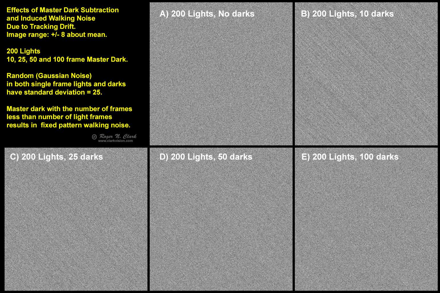
Tracking drifts, e.g. from a polar alignment error and no autoguiding, results in fixed pattern noise shifting from frame to frame. Depending on the nature of the pattern, shifting can reduce it, effectively eliminate it, or the pattern is not eliminated and results in walking noise. Examples are shown in Figure 5. Because the no dark subtraction (Figure 4a) does not have any pattern noise, no walking noise is seen. The Master dark, however, has residual noise, which induces walking noise (Figure 5B -5E). More frames in the master dark reduces the problem, and when the number of darks is about 50% of the number of light frames, the induced walking noise is small.
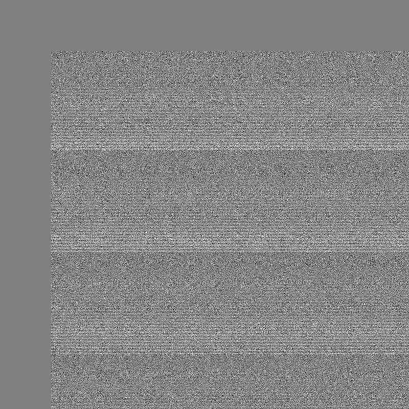
Next, I explore the effects of banding noise (pattern in Figure 6). A single light frame with noise = 25 with the pattern is shown in Figure 7, after the frame has shifted 100 pixels due to tracking drift.

Some say that a low number of darks, like 25 can effectively remove pattern noise. An example of subtracting a 25-frame master dark from a "light" frame is shown in Figure 8. The idea is verified: there is no apparent pattern noise in the dark subtracted image.

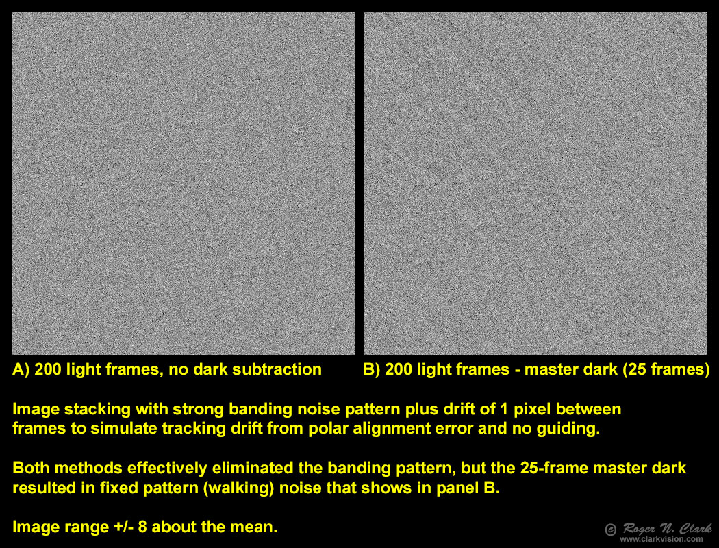
Effects of tracking drift on noise is shown in Figures 9, 10 and 11. The whole point of multiple exposure is to stretch the image to bring out more faint detail. A stretching result is shown in Figure 11, where we see induced walking noise from the 25-frame master dark. This shows that if the sensor has good on-sensor dark current suppression with low pattern noise, it can be best to no use dark frames.

Next I investigate pattern noise that appears random. Another image was created with random noise with a standard deviation = 25 (Figure 12). This image was added to lights and darks to simulate random-looking pattern noise.
Pattern noise that varies from pixel to pixel (e.g. Figure 12) turns into walking noise if not dark subtracted (Figure 13). Dark subtraction can eliminate this if the master dark is made at the same temperature, then the induced walking pattern noise as shown in Figure 5 would be the remaining noise.
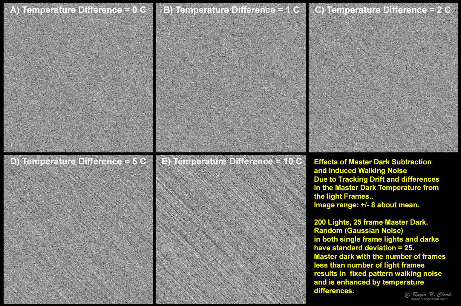
Dark current doubles for every increase in temperature of 5 to 6 degrees Centigrade. This means any pattern noise will be different intensity if the master dark is made at a different temperature than the light frames. With a tracking drift, walking noise is apparent and increases with temperature difference between lights and darks (Figure 14). For cameras without active cooling to hold the temperature of the sensor constant, for example consumer digital cameras like DSLRs and mirrorless cameras, it is difficult to keep the master darks at the same temperature as the light frames. In a typical imaging sequence, such cameras will heat up 5 to 10 degrees C in short time (e.g. Figure 15), for both lights and darks.
Dithering is a method of shifting the field of view slightly during the imaging session to reduce pattern noise. While dithering can reduce pattern noise, how often a new position is needed to have an effect is a question often asked. The equations that describe the situation is given in equation 3b when subtracting darks, and 3c without darks.
Results from stacking calculations are compared with models calculations using equations 3b and 3c in Table 1 below. For comparison with the above results, the calculations use 200 light frames with 25 dark frames and pattern noise with a standard deviation of 25 (Fixed Pattern, FP noise = 25). The random noise in the light frames and dark frames is also set to 25. If the sensor had no pattern noise (first line in Table 1), a stack of 200 images would have a noise standard deviation of only 1.768.
In the model, subtracting dark frames eliminated the pattern noise, but as we saw in previous sections, the master dark still has random noise that becomes a new fixed pattern noise. Dithering improves that induced fixed pattern noise (see Table 1, lines with 200 lights - 25 master dark). But subtracting a master dark will never reach the ideal noise level of line 1 in the table.
However, the situation is worse if no darks are subtracted (see Table 1, lines with no darks). The pattern noise is reduced by dithering, but clearly dark subtraction is a better method to reduce noise. If there is tracking drift, the walking noise will show (e.g. Figure 13).
         Table 1
                               image set    eqns 3a, 3b, 3c
 # lights     # darks          NC Standard  NC Model standard  Fixed Random Pattern   Dither
                                Deviation   Deviation  Eqn     standard Deviation   Positions  ndither

200 lights,  0, no darks         1.768        1.768    3c            0.0                0        1    Best: sensor with no pattern noise

200 lights - 25 master dark      5.283        5.303    3b           25.0                0        1
200 lights - 25 master dark      3.944        3.953    3b           25.0                1        2
200 lights - 25 master dark      3.377        3.385    3b           25.0                2        3
200 lights - 25 master dark      3.065        3.062    3b           25.0                3        4
200 lights - 25 master dark      2.853        2.850    3b           25.0                4        5

200 lights,  0, no darks        25.095       25.062    3c           25.0                0        1
200 lights,  0, no darks        17.745       17.766    3c           25.0                1        2
200 lights,  0, no darks        14.481       14.542    3c           25.0                2        3
200 lights,  0, no darks        12.574       12.624    3c           25.0                3        4
200 lights,  0, no darks        11.317       11.319    3c           25.0                4        5


Note: the small differences between image set noise and model equation noise is due
to the sample sample size and random numbers in the image set.
Notes: 1 dark frame with random noise =25 and fixed pattern noise =25 has a standard_deviation=35.349. The master dark with 25 dark frames averaged would have a standard_deviation =25.454 with fixed pattern noise. Increasing the number of dark frames will not reduce the noise below 25.
It is clear from Table 1 that dark frames and dithering have limits and that a sensor that has no or very low pattern noise can produce lower noise stacked images with no dark frames subtracted. Many modern cameras meet this requirement.
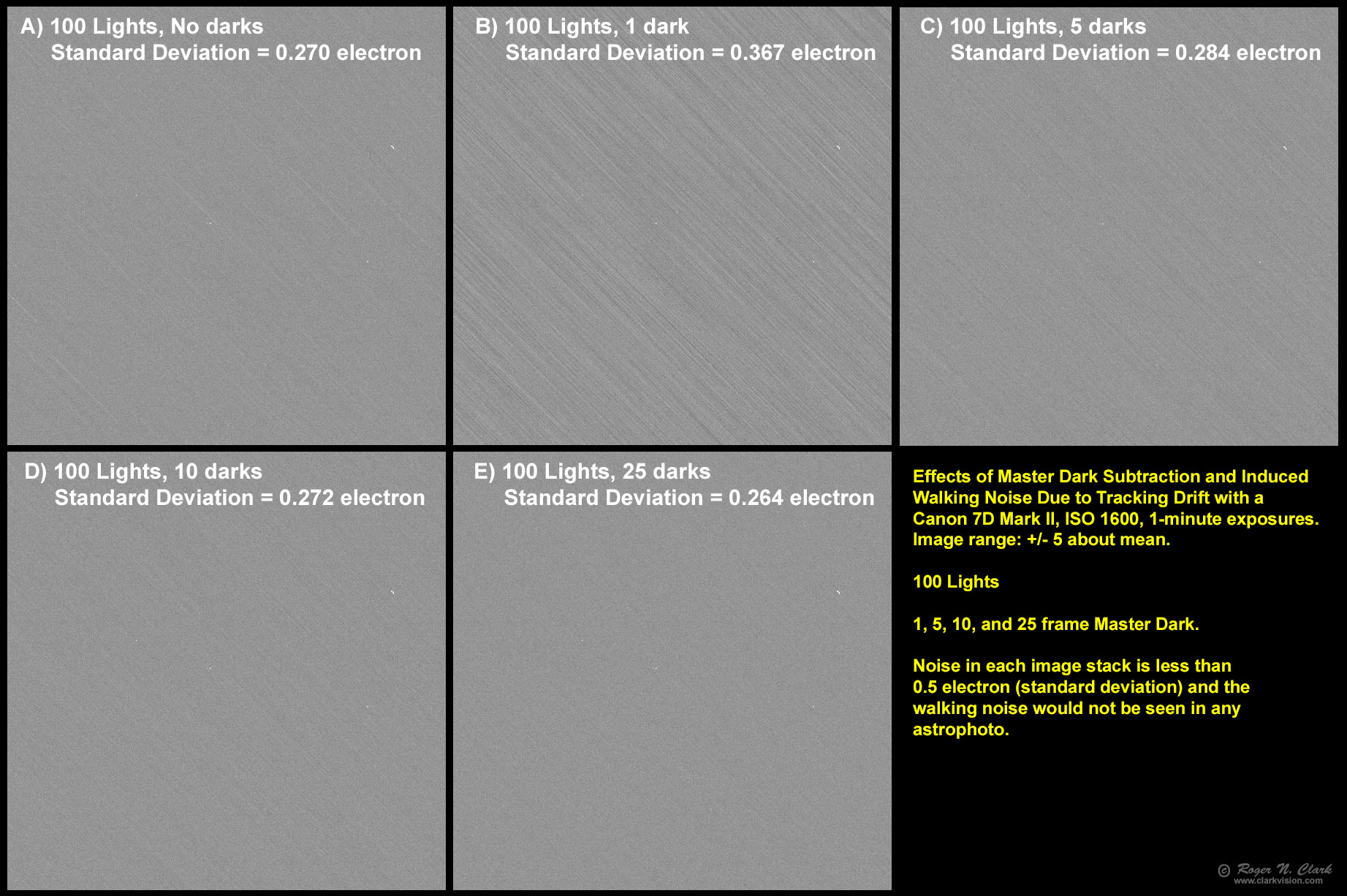
The models above, while generating example pattern and random noise are fine, but how do real cameras perform? Here I'll show results from a Canon 7D Mark II. A sequence of 150 exposures were made, each 1-minute at ISO 1600 with the lens cap on at night. Fifty frames were reserved for making master darks and 100 frames were considered light frames. Stacks of light frames and light - master darks were calculated from this set of images using raw linear data. Results are shown in Figure 16. The pattern noise in Figure 16 with no dark frame subtraction is negligible for any real world astrophoto imaging. Similarly for the images with dark frame subtraction. The inherent pattern noise in the 7D2 shows only about 1/4 electron standard deviation in 100 minutes of exposure time. As we learned above, master dark frames add random noise which becomes induced pattern noise. Here we see that there is some very low level pattern noise in the 7D2 (evidence from Figure 16, panel A) and the master dark frame can reduce that. We see with 10 dark frames in the master dark has subtracted the residual pattern noise in the 7D2, but the induced pattern noise results in about the same random noise (and apparent intensity of the banding noise) with about 10 darks. The noise, including pattern noise, is slightly below the no dark stack when the number of master darks is 25 (Figure 16, panel E).
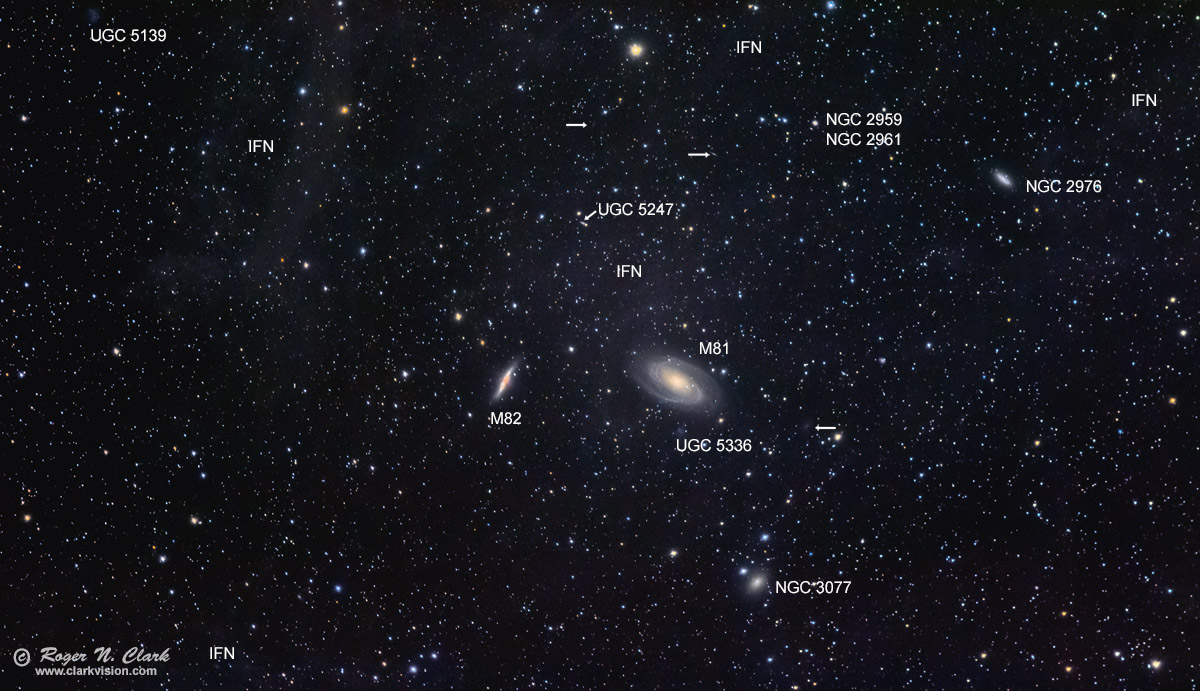
The pattern noise illustrated in Figure 16 will not be seen in even deep astrophotos, as illustrated in the M81, M81 and the Integrated Flux Nebula shown in Figure 17. The integrated flux nebula registered less than 1 photon per one-minute exposure. Even at 1/4 photon per exposure, the photon noise would be 3.4 electrons, or over 12 times higher than the noise from the camera.
While modern CMOS sensors show incredibly low noise, there may be situations where dark frame subtraction is of benefit to astrophotography images, but this is not always the case. Dark frame subtraction reduces pattern noise but increases random noise and can induce pattern noise when the number of dark frames is less than the number of light frames, and when the dark frames do not exactly match the temperature of the light frames. For better sensors the pattern noise may be so low that including dark frames can increase noise, in some cases by many factors (e.g. 3x, 5x, or more). That means the changes in low light sensitivity for the smallest signals in a stacked image can be many factors different depending on the sensor, if dark frames are used or not, and how many dark frames are used and what their temperatures are relative to the light frames. As sensors become better, with better On-Sensor Dark Current Suppression Technology, and better pixel to pixel uniformity, use of dark frames will do more harm than good.
In researching camera performance for this articles, I discovered another induced pattern noise source: the raw converter. Sensors include masked pixels around the edge of the sensor. Raw converters use the data from those pixels to find the electronic dark level, but just as pixels throughout the image are subject to noise, leading to error in the electronic zero level, the edge pixel measurements also include noise. During raw conversion, depending on how those edge pixels are treated, a fixed pattern noise can be generated, for example in one channel. So a sensor may show low random noise and low banding noise (e.g. the Canon 7D Mark II) but show banding noise in raw converted images. The problem, at least with the 7D Mark II seems to be affected by the battery charge level, with banding becoming a problem at low battery levels, and depending on how the raw converter treats the data.
The Night Photography Series:
| Home | Galleries | Articles | Reviews | Best Gear | Science | New | About | Contact |
http://clarkvision.com/articles/dark-frame-subtraction-vs-no-darks
First Published November 28, 2021
Last updated April 22, 2022